
|

|

|
|
|
|
|
| Home | Manuals | Supplies | Search | Consult | Contact | Testing | Service |


Modern Aeolian |
|
It is highly recommended that ALL of the following information be read BEFORE attempting to remove the piano action from the piano. Having a thorough understanding of how all of the various parts 'interact' with various other parts will make it much easier to both dismantle and re-assemble the piano. While the upper section of the modern Aeolian player 'can' be removed, I would strongly recommend against such an action. That said, let me explain the best way to approach removing the 'piano' action. First, I recommend having a second set of hands available. While this isn't absolutely necessary, it does make the job much, much easier. Second, to aid in my explanation, I have edited a couple of pictures. The one below shows the left side of the upper section. An explanation of the various points is below the picture.  SPECIAL NOTE: If your player has an Automatic Shut-Off device or a Repeat/ Replay Switch, the hoses that are connected to these devices DO NOT have to be removed. Also, in some models there is a piece of wood in front of the player platform which must be removed before beginning the dismantling procedure. And, some models have aluminum braces which secure the spoolbox to the back of the piano. These must be removed. A. These three screws secure the air motor in place. It is recommended that they be removed before removing the chain. That way, the chain won't get stretched. Also, not the direction of the links so it gets put back the same way. After the screws (and felt washers -if present) are removed, disconnect the chain at the top gear and lay it over the chain idler arm. Then lift the motor up and out of the piano. Normally, the hose comes off at the bottom, where it attaches to the air motor governor. B. These two screws secure the Bass Soft device to the side of the piano. Normally there are felt washers between the device and the side of the piano. Often, these felt washers are not glued in place, and they will fall into the piano unless care is taken when the screws are removed. However, do not remove the screws at this time. There are three hoses and one piece of linkage that are connected to the Bass Soft device. When removing the large vacuum supply hose, first attempt to "push" the hose further onto the fitting. Do not attempt to just 'pull' it off. With a little bit of patience, the hose will normally come 'unsealed' from the brass fitting. Then it can be pulled off. If the tubing is fairly old, it might crack, in which case it will have to be replaced. The other two tubes are connected to the valve blocks. Here again, 'push' the tubing further onto the fitting to loosen it first. Then pull the tubing off. Now you can remove the two screws and washers (if present). Note that the end of the piece of linkage that's attached to the metal flange finger has a 'hook' shape. By rotating the bass soft device 90 degrees to the right, you can easily separate the linkage from the device. Now you can remove the device from the piano. C. These two screws secure the left side of the platform to the piano. They can be removed at any time during the dismantling procedure. D. In most modern Aeolian players, there is a nut at this point. Typically, the nut is connected to a threaded rod that is secured to the keybed of the piano. Under the platform there should be another nut on the threaded rod. This nut serves as a support for the platform, to prevent the platform from sagging down in the middle -because of the weight of the spoolbox, tubing, transmission, and other attaching parts. Remove the nut if present. We will be discussing the threaded rod later. E. Connected to the air motor governor is a large vacuum supply hose. Due to space limitations, this hose is difficult to loosen. Often, a thin-bladed screwdriver is needed to loosen the seal between the hose and the brass elbow. In some cases, it's actually easier to remove the hose from the other end (see picture below), where it is attached to the lower section (the exhauster assembly). Then, the hose can be 'twisted' off of the fitting on the governor. In either case, if the player is more than 25 years old, it's wise to have a piece of replacement tubing on hand. The hose is 3/4" ID and approximately two feet long. (It's #19T tubing -click here for tubing. F. This points to a leather nut that's used to secure the Tempo control linkage to the air motor governor. Again, due to space limitations, this nut can be difficult to remove unless you have your hand at just the right angle. (I find it easier to remove it with my left hand.) Once it's off, slide the linkage back and out of the lever to which it is connected. Now that all of the pieces on the left are disconnected and/or removed from the piano, you can easily access the screw that holds the left side of the Honky-Tonk (or Mandolin) device in place. Typically, there is at least one soundboard button -which serves as a spacer- between the aluminum rail and the side of the piano. This part is not usually glued in place. So, use care when removing the screw to prevent the button from falling down inside the piano. We'll discuss removing the device at a later time. The picture below shows the right side of the upper section. An explanation of the various points is below the picture. 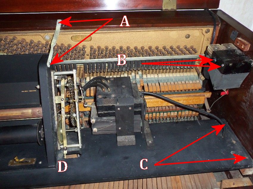 A. These are the screws that secure one of the spoolbox brackets. Depending on the model, there might be two brackets, one bracket, or no brackets. If present, remove the brackets. B. This is the Treble Soft device. Refer to Step 'B' above for directions concerning removal of this device. C. These are the two screws to secure the right side of the platform to the piano. Remove them. D. Refer to Step 'D' above. The picture below shows the right side of a more complex version of the Standard Aeolian action. It has been included in this treatise because it shows the location of the Honky-Tonk mounting screw and the platform support nut, which were both mentioned earlier. Pertinent information concerning these parts is below the picture. 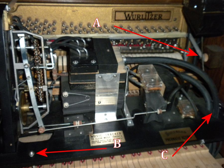 A. By this point in time, the Bass and Treble Soft devices and the spoolbox support brackets should have been removed. Also, the screw that holds the left side of the Honky-Tonk rail in place should have been removed. Now, remove the screw that holds the right end of the device in place. Again, take care not to left the wooden button fall down into the piano. Now, the only thing keeping the rail from being removed from the piano is a wire that's connected to the left end of the rail. Typically, this piece of wire (which is used to move the rail up and down) has a series of bends in the end that 'hold' the wire to the rail. By lifting the right end of the rail straight up and over to the left end of the piano (pivoting on the wire), the rail can be released from the wire without 'unbending' the wire. Sometimes there are two series of bends. So, you have to lift the rail up, side the wire over, let the rail back down, side the wire over, and lift the rail up a second time to free the wire from the rail. B. This shows the location of the platform support nut. As mentioned in Step 'D' above, it is one of two support nuts. In this photo, you can just barely see the threaded rod below the platform. However, directly under the platform is another nut, upon which the platform rests. This nut, and its mate on the other side of the spoolbox, can be adjusted so the platform is perfectly level. What's important to understand at this point in time is that the entire platform will have to be raised up at least two inches (2") above the top of the threaded rod before the platform assembly is moved towards the front of the piano. (But I'm getting ahead of myself.) C. In most instances, these two hoses do not need to be disconnected when moving the platform forward. However, if they are preventing the assembly from coming forward at least four inches, they should be disconnected at the devices to which they are connected. (Sometimes it's just easier to disconnect them before attempting to move the platform....) The picture below shows the components of interest in the bottom portion of the piano on the left hand side. An explanation of the various points is below the picture. 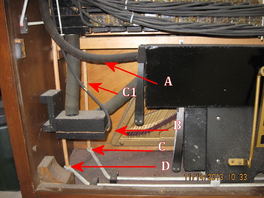 A. This is the air motor vacuum supply hose. It connects to the air motor governor. In some cases, it's easier to remove this hose where it attaches to the back of the exhauster assembly before attempting to disconnect it from the air motor governor. Usually, twisting the hose where the point of the arrow is located will free it from the brass elbow to which it's connected. Once it's loose, the whole piece of tubing can be twisted to free it from the connection at the governor. Read on....
B. This tube controls the functioning of the Cut-Out Valve. The other end of this tube connects to a pallet valve that's mounted on the underside of the platform. In some cases, moving the platform towards the front of the piano stretches this tube to the point where it pulls out the horseshoe nails that secure the hose to the underside of the platform. So, it's always best to disconnect the hose at the Cut-Out device before moving the platform. While the picture below is totally out of focus, you can see the other end of this tube and the pallet valve that's mounted under the platform. You can also see all of the note tubing, which will be covered in the next segment of this treatise.(Return to Step 'D' Above)  C. & C1. This is the Sustain Pedal and the Sustain Pedal Rod. It's recommended that the rod be disengaged from the metal trapwork ('C'). This is accomplished by lifting the rod upwards and away from the metal lever. Many of the Aeolian players also have an Automatic Sustain Pedal device (not pictured here) which engages with the Sustain Pedal Rod. This device straddles the metal trapwork and makes disengaging the wooden rod quite difficult. For this reason, I recommend that the Auto Sustain device be removed from the piano before proceeding. Once the wooden rod has been disengaged, the Manual Sustain needs to be loosened. Refer to 'C1' in the picture above. This is an 'eyehook' that is screwed into the wooden rod. Running through the eyehook is a piece of threaded rod with leather nuts that are used for adjusting the operation/position of the Manual Sustain lever (located in front of the piano keys and marked "LOUD"). It is recommended that the lower leather nuts be backed off from its current position, which will allow the rod to drop down about an inch. This will make it easier to disengage the rod from the piano action now and re-engage the rod when the action is put back in the piano. D This is the Soft Pedal Rod. Lift up on the wooden rod to disengage it from the metal trapwork. Once this is done, it will normally fall enough that it disengages with the hammer rail (where it makes contact at the other end). In some cases, the hammer rail must be manually lifted upwards to disengage the rod. Once it is disengaged, the rod can be removed by lifting it up and out of the piano from the top (by the hammer rail). Finally we're just about ready to move the player platform. By now, the person who was enlisted to help is probably wondering what they're going to be doing. Personally, I think it's important for them to see all the steps leading up to the actual removal of the piano action. However, they really won't be needed until after the platform has been moved forward about four inches (4"-6"). But before proceeding, take a very thick blanket and cover all of the area in front of the player platform assembly. You will be resting the platform on this blanket and there are sharp protrusions (mainly the Tempo linkage on the left end of the assembly) on the underside of the assembly that can damage the keys and cheek blocks. This next step is critically important and is where a second set of eyes comes in really handy. If done incorrectly, some very time consuming damage could be done to the tubing on the underside of the platform. Recall the picture above that shows the tubing on the underside of the platform. Keep in mind that as you are lifting the platform 'up' and then 'forward' (towards the front of the piano), you will have to lift it high enough that the two platform support rods (See above-click here) clear all of the note tubing and the tube leading to the cut-out device. Failure to take this precaution could lead to the puncturing of one or more of the tubes, which are exceedingly difficult to repair.
SPECIAL NOTE: It was brought to my attention that some units have a bracket (see picture below) that's used to help prevent the note tuning from rubbing against the first and last keys. While these brackets can be difficult to remove, it is highly recommended that the screws which hold them in place be removed before proceeding to the next step. 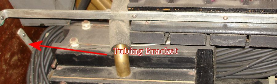 Now, lift the platform assembly straight up. I place my left hand under the platform (to lift it) and my right hand on top of the spoolbox (to keep the assembly level). No doubt you will feel the note tubes resisting you as you lift the assembly 'up'. This is normal. After you have raised it high enough to clear the note tubing, move the assembly as far forward as possible and rest it on the blanket. It has a natural tendency to fall backwards (towards the piano action) and this is where the second set of hands comes into play. From this point forward, until the piano action is safely removed, your 'helper' must keep the player assembly from falling forward. (In cases where I didn't have a helper, I've used rubber trackerbar tubing to hole the player action away from the piano action. I accomplish this by wrapping the tubing around the upper half of the spoolbox and back uder and around the front legs of the piano. Naturally, there may be other ways to handle this problem. Use your imagination....) Removing the piano action is a fairly straightforward task, but there are a couple of extra steps that need to be taken. One involves the Bass and Treble Soft linkage, which should be removed prior to removing the piano action. There are two ways to accomplish the task. One is to unscrew the leather nuts that are used for adjusting the soft controls. The other is to simply back the linkage out through the rubber grommet in the metal flange that's screwed to the pieces on the hammer rail. I find that the second option is much easier. The second precaution involves the dampers. Since there is very little room to work, you have to be extra careful and ensure that the dampers clear the action support rods and the strings while extracting the action. Take your time. After coming this far, it would be a shame to bend a damper wire or break a damper lever or flange. Also, having removed many dozens of these actions, I've found that the company didn't do a very good jog of sizing the action brackets where they attach to the action support rods. They are always 'tight', and basically you have to pry the brackets off of the rods. Be sure to do this evenly, so as not to twist the action. BTW, after the action has been removed, I use a wooden or metal rod to support the player action while the repairs to the piano action are being done. (Give your helper a break... :-) Once the repairs to the action have been completed, putting everything back together is basically the reverse of taking it apart. One of the more difficult aspects of this job is getting the Sustain Pedal rod aligned with the Sustain lever in the piano action. This should be done just prior to pushing the action back onto the action support rods. The Soft Pedal rod can be installed after the piano action is secured in place. This ends this treatise. If you have any questions, do not hesitate to write to me. |
![]()

![]() ..To
The Top of this Page . . . . . . . . . . .
..To
The Top of this Page . . . . . . . . . . . ![]() ..To The HOME Page
..To The HOME Page
|
Since "Player-Care" is an internet business, I prefer that we correspond via E-Mail (click here to fill out the 'Request Form'). However, if I'm not in the middle of some other activity, you can reach me at 732-840-8787. But please understand that during the hours from 8AM-5PM EST (Mon-Sat), I'm generally quite busy. So, I probably won't answer the phone. If you get the answering machine, please leave a detailed message stating the reason for your call. Also, repeat your name and phone number clearly and distinctly. By necessity, I prioritize everything in my life. And, if you call and just leave your name and number, and ask me to call you back, it might be a day or two before I return your call. Why? Because I don't know why you want me to call and I might not be prepared to assist you in an effective and efficient manner. If you leave me an E-Mail address (which I prefer), spell it out phonetically. The more you do to help me, the more I can help you in return. Don't rush. You have four minutes to record your message. |
|
407 19th Ave, Brick, NJ, 08724 Phone Number 732-840-8787 (Voicemail Only, No Texts) |
