
|

|

|
|
|
|
|
| Home | Manuals | Supplies | Search | Consult | Contact | Testing | Service |
|
IMPORTANT NOTES: Player-Care accepts no responsibility for the accuracy or validity of the following procedure. It was written in the early 1980's and many things have changed since then. This information is only presented to familiarize people with the various steps involved in the restoration of Standard valves. A number of the materials mentioned in this treatise were found to be unsatisfactory less than twenty years after it was written. |
|
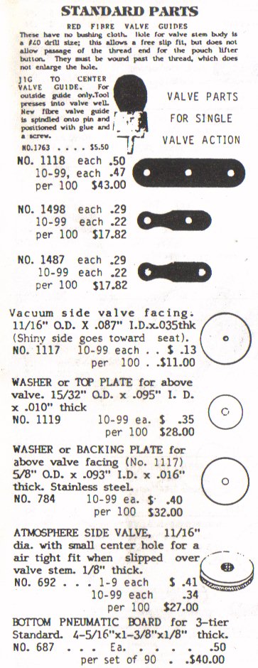
To determine need for replacing the main valves, thus called "secondary" valves, when there are primary valves on top, the first step is to remove the primary valve chest from the secondary chest. This is done in the following manner: Remove the complete top action from piano. There are four large oval head wood screws on the left side of the player stack which go through the pouch board and into the gasketed vacuum supply block. There are also small screws surrounding the pouch board, but these do not affect removal of the player stack from piano. Remove these four large screws, and one large vertical screw on the right side of the player stack which attaches to the rear top of the cheek block of piano case. These are the only screws which attach to piano, with exception of the metal bracket at the top left of the spool box which supports against the piano harp. Find the two control wires (tempo and shift control) which come out under the shelf under the pneumatic roll mo- tor. Disconnect these, and the 3/4" hose going to the motor. Now the entire stack will be free to lift out of the piano. In order to separate the spool box and primary valve section from the secondary valve chest, there are five vertical screws which go through the primary chest into the secondary. These are located through holes in the spool box shelf -- two at each extreme end and one at the left side of the spool box. The holes in the shelf allow a screwdriver to be placed through them to turn the screws at the top of the primary chest. Next, there is a row of smaller screws on top of the "L" board which gaskets to the top of the secondary chest. When these are removed it leaves the main valve chest and the corresponding pneumatic decks standing alone. The object is to determine the amount of leakage in this, in order to decide the necessity of rebuilding the secondary valves. From this point, the discussion will be entirely devoted to the secondary valve chest, with the primary valve section, remaining apart. You will need to remove the junction block at the left which is screwed to the key bed and has the main hose connection below. Disconnect the 1-1/2" hose and retrieve this block temporarily for use in attaching to the valve chest again for testing purposes. With masking tape covering the 88 holes on the top which gasket to the "L" board, this seals it in the same manner as the music roll would cover the tracker bar with blank paper. There should be no leakage under this condition (making the hopeful wish that everything is perfect). That is, when the nipple of the junction block is sucked on, with the valve chest laying on the work bench with the pneumatics facing up, all valves should seal tightly. You should be able to insert the 1-1/2" I.D. rubber hose on the nipple and draw on it with your own lung power and hold the tightness for 2 seconds with one gulp of air. If you cannot, then it is due for a valve rebuilding job. As usually is the case, it is long overdue. If it is tight with the "two second" test, you are very lucky and can avoid doing anything to the secondary valves, and perhaps need only to recover the striking pneumatics, if the cloth has deterioration of the rubber coating or cracks in the folds. It should be emphasized strongly that the leaking cloth of these pneumatics has nothing to do with the tightness (minimum loss of vacuum seal) of this secondary chest assembly. The potential for individual pneumatic cloth leaking has no effect until the pneumatics are in closed position, caused by opening the hole for pouch and valve action. It would be pointless to only recover these pneumatics, even when it needs it, hoping for an improvement in overall playing performance, it will not work effectively until a vacuum within the chest can be exhausted and held; this is dependent on the valves. Since the labor involved in rebuilding the secondary valves to all seat tightly, is the most precise and demanding job, time-wise, over anything else that may have to be done, you will want to approach this carefully so that you will not have wasted your efforts by doing a poor job. This is what this essay is about: a guide to the method that will lead to success. Having determined that a valve job is eminent, you proceed by removing the pouch board. (This is shown on page 38 of "Rebuilding the Player Piano", uncovering the valves as shown on page 34.) Each of the metal valve plates are screwed and sealed to the top of the valve well. When the wood screws are removed, the plate can easily be pried off. (This is only in the case of the original sealer.) Place a screwdriver blade against the edge of the plate and twist the blade; it should pop off and allow you to have in hand, the complete valve assembly. By unscrewing the wooden pouch button (counter-clockwise) the stem will pass through the red fiber valve guide. The valve opposite this slips off easily, leaving the stem with only the main valve attached. You will notice that it is secured by the 7/32" diameter force-fit collars. At this point it is possible to make a test on the seating surface of this valve to prove the leakage. To make this test, use a 3/4" OD elbow with one end surfaced perfectly smooth and flat. This can be accomplished by raking the end over a file. Onto this surfaced end, place the valve, in the same manner that it would ordinarily seat on the metal plate. By sucking lightly on the other end, the valve should seat tightly. If you cannot place your tongue over the other end and trap the vacuum within for a few seconds, it is not tight and proves that the outside air is somehow managing to pass through or around the leather valve seat. For control, use your thumb instead of the valve, and you can feel how 100% tight feels. The leather valve washer may appear to the eye to be perfect, but this test proves the fallacy in this thinking. Obviously, it is not laying flat enough at the low vacuum, or else it is seeping past the valve stem as it goes through the center hole of the leather. Remember that the normal playing vacuum to seat this valve is only about eight inches of water gauge reading (the vacuum necessary to lift a column of water in a tube, eight inches high (a vacuum cleaner may pull nine or ten times this amount). The basis of seating under this low vacuum condition is the flexibility of the edge of the exposed leather to draw away from the metal backing plate under vacuum attraction to meet the surface of the test elbow (or metal valve plate.) Also, the flexibility of the body of the valve to tilt and to compensate for any misalignment of the valve guides. Therefore, the valve must not be rigidly attached to the valve stem. It will not be on the original valve, and as you can see: Hold the valve assembly by the stem and grasp the valve with your other hand: it can move slightly away from the normal right angle to the stem, and stay there. It is important to remember this later when you replace the old leather with the new. You will need to remove this valve washer from the stem. This is done by clamping the threaded end in a vise. It is advisable to line the jaws of the vise with thin wooden boards to prevent damage to the thread. Next, place parallel jaw pliers over the force-fit collar. Twist alternately clockwise and counter-clockwise, the motion of the collar, at the same time, pulling toward you. It can easily be drawn off the stem. Be sure you have precision pliers: the common household variety is much to sloppy (slip-joint type) and mismatched at the end to grip the edge of the collar when you get to the second one. The first collar is the stop collar for the loose valve (or exhaust valve). The second collar removal allows you to remove the intake valve; stack of parts which consist of the packing washers on either side (usually made of thin leather) and the top plate and the backing plate, which are on either side of the leather. The collars are usually reusable, but if there is an occasional one that will not later go back on tightly, new ones are available from Player-Care (stock no. 1111) as well as the valve leather replacement. No. 1114 (Out of stock as of 08/27/2015). The top plate and backing plates are reusable, as long as they are still flat and are cleaned of dirt or corrosion. New packing washers, No. 1112 (Out of stock as of 08/27/2015) should be ordered, to replace the leather packing washers. If, for some reason, your valve construction is made of leather, felt and fiber glued together, this should be disposed of altogether. Instead, also order new top and backing plates, and reconstruct as per the diagram below. You need not be concerned about the possibility of a change in total thickness of these new parts, affecting the relationship to the original surroundings. Remember that the force-fit collar, nearest the threaded tip of the valve stem, never is to be removed. When new parts are on hand, they may be threaded on in order and finally secured by driving on the force-fit collar to again compress them together. The secret to the operation of driving on the force-fit collar, is not to compress these parts too much, so as to retain the ability to tilt or wobble, as previously mentioned. The easiest way to do this is to lay the collar over a hole drilled in a block of metal and insert the smooth end of the valve stem on top of this and tap with a small hammer on the threaded end. The hole in the block of metal should be sufficiently deep and of a diameter not to jam. After the collar is near the point that it will start compressing the sponge packing washers, go very slowly and watch it from a side-wise angle, and just as the sponge starts to compress, stop. The compression of the sponge washer (no. 1112 -NOT AVAILABLE) will serve to keep a tight seal, preventing any leakage through the center hole of the valve leather by virtue of the fact that the sponge seals against the backing plate, the backing plate in turn seats against the reverse side of the leather, and in turn, the top side (shiny side) of the leather against the top plate, and then against the other sponge washer. There can be no leakage sideways between the metal, leather and sponge washers. Now you are ready to place your first new valve back onto your test elbow for comparison with one of the old ones. It will be rewarding to feel the difference in tightness and be assured of your accomplishment. However, you are not ready to replace the "loose" valve without first setting the position of the "stop collar" for this. This calls for some "time out" for some trial and error work in making a depth jig for driving this on. It is done in the same manner as the previous collar, except you need to drill another hole in your block of metal, so the smooth end of the valve stem can be placed over the collar and be driven to the bottom of this hole, and end up in the right position. You can tell approximately how deep to drill the hole by inserting one of the original valves, so that the stop collar will rest just off the surface of the block. This may not always be correct if an additional thickness of the new leather or sponge washers results. The object is to have the proper valve travel. This should be approximately a 0.038"-0.045" (see Note 1 below) movement when popped back into the valve well and jiggled against the valve plate, held down temporarily by hand. If too little or no valve motion, then the hole will have to be drilled deeper, resulting in the two replaced collars being closer together than originally. And if too much valve travel; another hole should be drilled to determine that the collar is not driven on as far. The "test" travel should be on the plus side, to allow for any differences between one valve and another, and thereupon regulated by placing shims ahead of the "loose" valve. Each one will be somewhat trial and error, but it is easier to add and subtract paper shims than to be moving the collar about after it is once driven on. The paper shim, stock no. 1236, is a good one for this, as it will allow .010 increments of shimming. The loose or outside valve can be entirely replaced with stock no. 693. You may also reuse some of the original leather packing washers (replaced by the No. 1112 sponge) for the purpose of shimming, if they are not too rotten with age. If the felt bushing hole In either of the fiber valve guides has been "moth-eaten" or severely worn, you may want to consider replacements for these: Stock nos. 1109 and 1497 (NOT AVAILABLE). The flexibility of the secured valve will overcome minor misalignment problems due to wear in hole of the valve guide. Although not absolutely necessary, it would add to tightness at low vacuum to insure that the metal valve seats are also flat. It rarely is; because the brass warps slightly with age. This results in high and low spots. This can quickly be realized by buying a 12" or 14" "mill file": laying it on a flat solid surface, and grasping the edge of the valve plate by your fingertips and scooting it across the file. The high spots, including the thin nickel plating will be skimmed off with the first lick, showing all the high spots. It may take as many as seven or eight more passes over the file to remove the last of the low spots. To prepare the raw brass surface against future corrosion, which the nickel plate prevented, it is not necessary to have them replated. A spray coat of stock no. 1700 McLube will do the job just as well. Spray five coats of McLube, with all the valve plates strung out on a newspaper. After the completion of each valve and proper shimming, the valve can be left in the valve well with the plate, awaiting resealing. To do this, use stock no. PVC-E Plastic Glue. Draw a bead of this glue around the edge of the valve well, making sure that it is between the screw hole and edge of the valve well. As the valve plate and guide is screwed on again, the excess glue will squeeze out. After the valve plates are all remounted, the wooden pouch button can be replaced by holding the stem with needle-nose pliers and screwing back on clockwise. To determine how much or how little to screw these on in relation to the pouch it will later come in contact with, you can use the following method: You can use a straight-edge with shims glued on each end of the straight-edge, which are equal to the combined thickness of the gasket plus the "dip" in the pouch. The old pouches rarely need replacing in the Standard Action. But, because they may be somewhat formed in the position surrounding the pouch button of the valve, they may be massaged with Dow Corning 3140 RTV (see 'Sealing Pouches') to make them softer and more flexible. In addition to adding a preservative for future life of the pouch leather, the sealer will seal the porosity and make it far less receptive to humidity changes and more responsive. However, do not add the sealer to the secondary pouches until completely finished with the restoration. The reason: it is very difficult to do any testing of the finished valve assembly when ciphiring occurs due to the pouch material being too tight. A normally porous leather compensates for the fact that there is no bleed in the secondary pouch system. The secondary pouch is controlled by the primary valve, which does have the bleed hole with each of its pouches. To make an accurate test of the secondary valve chest, the primary valve chest must be disconnected. If the secondary pouches have already been replaced with an airtight material or treated with something to make it airtight, it may be necessary to drill temporary bleed holes, to prevent ciphiring and spoiling the test. This is done in the following way: Use a #50 size drill bit to connect the vacuum side of the pouch board to the 5/32" hole coming from the gasket joint. This may be done just inside the area normally covered by this gasket on the edge of the pouch board. After the test these holes can be filled by a smear of glue. When the pouch lays down in the pouch well naturally, you can determine how much of the wooden button may go into the dip without danger of the pouch leather lifting it up. The dip allowance plus gasket thickness is going to be equal to the shim on the straight-edge. As each valve is pulled up by the stem with needle-nose pliers to seat against the metal valve plate, run the straight-edge over the top of this wooden button. If it hits, then you need to screw the wooden button on further. It should be a little below this for safety. The shims will rest on the edges of the chest board and the attached straight-edge wilt span across the three rows of valves. In preparation for testing the tightness of the replaced valves, the screw holes going through the chest to connect the tier boards are taped over with patches of masking tape and the pouch board is replaced. The left end supply channel block is replaced. The row of holes on the edge of the pouch board, which later connects to the primary valves is sealed with masking tape. Also the supply holes at either end going to the primary valve section are sealed. Although the repetitious work is out of the way, you can expect that there will almost always be some valves that leak for one reason or another. Perhaps a speck of glue on the valve leather, or some flaw to prevent the seating of the valve or a leak around the valve plate. The reason for leaking usually becomes apparent when the valve plate is again removed. These must first be tested with a listening test with the chest under normal vacuum, to determine which, if any, need further attention. You should power this test with a vacuum cleaner. You need low vacuum for a realistic test. Five inches of water lift vacuum would be ideal. The vacuum pull of the vacuum cleaner may be reduced by making a large leak hole in the line going from this to the player action. If you do not have a vacuum gauge to set the five inches, you could determine this by attaching the vacuum cleaner with the leak in the hose to the rebuilt bottom foot pump section, with all other smaller hose connections taped over. Five inches of vacuum should pull the reservoir one third of the way closed. With a constant source of vacuum for testing, this will allow you to have both hands free. Your hands are used to guide a listening tube along each of the atmosphere valve ports to detect any leak. One hand to hold one end in your ear and the other to move it along the board. The listening tube is simply a 1/4" to 3/8" I.D. section of tubing about 16" long. A stethoscope will not work unless the listening end has been remove, exposing the open tube. If the valve is leaking you will hear a hiss with the listening tube. If you do, then for the sake of speeding up the process of elimination, you should place masking tape over the hole which normally goes to the pneumatic and also over the valve guide and tip of the valve stem to completely seal the atmosphere valve hole, thereby confining the leak internally. The elimination of this leak may allow you to hear a smaller adjacent leak in the next valve. Keep passing overall the valves and sealing each one with masking tape until no leaks can be heard. At this point, the remaining valves which have not been taped, need no attention. The others can be reworked after opening up the chest again. The masking tape patches can be left in place while this is being done. After the pouch board is again replaced and you are back to the vacuum cleaner test, the individual "bandages" (masking tape over the previously sick valves) may be removed to find out if the individual operations were successful. When the last taped over valve has had its problems corrected, you should be able to hold the vacuum tightness easily with your own lung power, by sucking on the 1-1/2" hose which previously went to the vacuum cleaner. Run a strip of masking tape to cover the holes that connects to the pneumatics. A test may be made to test the sealing of the valves on the atmosphere side, before opening up the chest again. With the vacuum cleaner pulling the five inches of vacuum, you may start punching through the holes on the edge of the pouch board through the masking tape. You can watch the valve movement and listen for any leaks. There will rarely be any problems on this test. Although, don't expect any fast repetition, since there are no bleed holes in the pouch system. The object of this test would be to determine that when the atmosphere valve seats; with the passageway to the pneumatic blocked, there should be silence except for the thumping of the valve seating, and possibly a slight hiss through the hole going to the pouch, which is normal. After half a dozen of these holes are punched through they can be resealed before going on to more. If you do not plan on recovering the pneumatics on the tier-boards, the chest may be opened up again, and with all masking tape removed, screw the pneumatic section back on. If the pneumatics are to be recovered, you should remember not to glue the pneumatics back on the tier-board with the hinge end close enough to risk obstructing the movement of the valve stem behind it. It would also be wise to go along the gasket of the newly recovered deck board to suck out any debris with a vacuum cleaner before it could be sucked into the valves and cause them to leak. This concludes the secondary valve job. The rebuilding of the primary valves is another chapter. Once the primaries are again attached back on top of the secondary chest, they again become a part of the vacuum system. As a rule, the old primary valve leather will lose about four inches of vacuum until at least the exterior valve facing has been replaced. At least you will know that this portion is responsible for any additional drop in vacuum through leakage.
In some of the Standard double valve actions, there was a bleed cup placed in the 5/32" channel hole leading to the primary valves, at the point where this gaskets to the secondary valve chest: there, you will find this bleed cup, if it exists. There was about a 1/16" hole in this bleed cup. One would think, this might be restrictive of the passage of air or vacuum from the primary valves to the secondary pouch, but apparently does not affect playing performance. No one seems to know what the purpose of this was, and questions arise because of the fact that most identical player actions have this restrictive bleed cup missing altogether. One possible theory on this might be: That this was intended to solve a potential problem that would occur on rare occasions, when either through moving the piano, the secondary valves are disturbed, and because of the construction of the horizontal movement of valves, gravity does not contribute to the natural seated position of these valves, on the first occasion to play the instrument again. OR, through removal of the player action for service work on the piano action, the valves are similarly disturbed. Since, if the vacuum is lower in the primary chest than the secondary chest, the system would remain silent on normal pumping because of the loss of vacuum in the secondary chest through unseated valves. The vacuum for the primary chest is fed through the secondary chest, and therefore, a lower vacuum coming back through the primary valve into the secondary pouch cavity responds as if it were atmosphere, therefore trying to inflate the pouch which is counter to the valve trying to move in the opposite direction in order to seat. The restriction may be placed to conserve what little vacuum may be built up in the primary chest to allow it to build up more rapidly and reverse the situation of imbalance, so that the primary chest may sooner become equal. Without these bleed restrictions, it is still possible to right the situation with either of two ways: by furious foot-pumping to overtake the rate of lost vacuum through numerous secondary valves caught half-way between the two seats therefore, a wide open leak to atmosphere: or removing the player action screws and laying it down toward the keys to seat the valves by gravity, then carefully raising it back in place again. You may remove these bleed restrictions if you wish, because it is a rare situation, and it cannot be proven that beyond the purpose served, that it either contributes or binders the normal playing performance. Often there will be a green corrosion on this bleed cup rim where it contacts the leather gasket: this is a result of tanning acids left in the leather, which over a period of many years, builds up this deposit, but it rarely affects the size of the hole. Questions always arise on the matter of how to determine when the secondary valve is moving 3/64". You may order stock no. 1474 valve gapping tool. This is inserted before the wooden pouch button is returned to the valve stem. The .035 thickness of this gauge plus the .010 thickness of the top plate will give approximately the 3/64" space. Another method would be to space the travel by trial and error, so that with the addition of a paper shim thrown in temporarily between the valve plate and the valve surface, the movement is practically none. There needs to be enough give on this test to make sure that the shim is not holding up the valve plate. Once one valve has been set, you may be able to compare the remaining valve spacing by referring to the "jiggle" or feel of the first one. Actually the 3/64" movement represents a "happy medium". It allows a maximum plus or minus error of .010 either way, without adversely affecting the performance. So you can see by this, it is not all that critical. If you "shoot" for this 3/64" travel visually, you should come close enough to this, not to be concerned. Visual or adjustment by "feel" is much faster than using a gauge, but the gauge is made available for those that may not otherwise trust their judgment. All leather is porous to some degree. The original leather used in the Standard action for seating against the valve plate was a firm calf skin which reduced the porosity seating against the plate to a very low degree. However, it has been determined by Player Piano Co., that a more suitable leather for this. is a kid skin with a patent leather finish. This shiny-non-porous surface is 100% airtight. The use of the No. 1114 valve leather replacement should result in a tightness overall in the valves seating, which will surpass that of the player action when it was "factory new". On the matter of replacing the fiber valve guides with new ones (nos. 1109 or 1497) the guide hole in these replacements are without the bushing cloth lining. Time has shown that similar valve guides in other types of player actions of similar function, which have eliminated this felt bushing, have shown no appreciable wear over the years, in comparison to cloth bushed guide holes of the Standard action. Therefore, the decision to eliminate this feature, in the making of replacements. It is also much easier to ream these holes, when necessary (there were a few variations of valve stem diameter used). Not only is this cheaper to produce (and therefore hold down the price) but over the long run, actually will last many years longer, and in addition be impervious to the possibility of being nibbled away by the almost invisible felt mite, which in unusual cases has caused total devastation in some player actions (after the felt feast). However, it is reluctantly pointed out, that there is one negative feature also: This requires that in order for the wider, threaded. end of the valve stem to pass through the unbushed hole, it must be "wound" through, thus it forces threads upon the fiber, but does not affect the guiding area. Moths are frequently blamed for the destructions of all felt used in player pianos. Actually a moth is too large to enter most felt areas except the piano hammers, where eggs are laid and larva feeds on the felt later. Certainly it would be impossible for a moth to crawl through the largest opening in the player action the atmosphere valve port. If there is evidence of felt damage, either in the valve guide bushings or felts under the piano keys, the possibility of active mites may be exterminated by liberally spraying stock no. 470 Moth Proof Spray. A useful tool for removing the original sealer used on the valve plates in the secondary chest is the stock no. 479 valve chest scraper, since there is less chance of gouging the wood with this tool than other means. You should check the side and end strips glued to this chest board; if the glue has given way, it should be split off and reglued. If this is the case, and excellent opportunity to run the board over a sanding machine to remove the sealer. If it appears to be cracked, but not loose, then a bead of glue run around on the inside of the chest should be sufficient. If gaskets are to be replaced, the cork-rubber composition is better than leather, because it is of a more uniform thickness and is not porous, as leather is. Stock no. 398 is suggested for the several gaskets used. This is a strip 4" by 54". If you will dab a little rubber stamp pad ink over each of the screw holes and the outline and press the gasket strip over it, it will be an easy way to locate and cut out the holes from this resulting imprint. The "L" board has one screwed and glued joint. The glued joint should be considered "suspect". Remove the few screws, then try to break it Not really try, but if the glue joint is defective, a light "rap" on both ends should prove or disprove the soundness of it.
Note 1. It is this authors opinion that the correct valve travel for the secondary valves is 0.040". Furthermore, I believe that all materials used in the rebuilding process should be as close as possible to the original materials. Synthetic materials have proven to be unreliable. Also, patent leather valve facings have a tendency to stick to the metal valve plate, and require more vacuum to pull away from the seat. Real leather does not have these problems. Note 2. Since the above treatise was written some forty years ago, it is not considered advisable (by this author) to use Neatsfoot oil on the pouches. I strongly recommend changing them regardless of how good they feel or how well they 'test'. Rebuilding the secondary valves is typically a once-in-a-lifetime job, and it would be sad to have to open the stack back up within just a few years to replace the pouches. Do everything while the stack is apart. Very Important Note: There are distinct differences between the parts for the Single and Double Valves in the Standard Action. When in doubt, it is always wise to send a sample, of the parts you want, to the supplier or retailer and let them pick the right parts for you.
   (The above prices are over forty years old.) |
We Gladly Accept These Cards

![]()
|
Since "Player-Care" is an internet business, I prefer that we correspond via E-Mail (click here to fill out the 'Request Form'). However, if I'm not in the middle of some other activity, you can reach me at 732-840-8787. But please understand that during the hours from 8AM-5PM EST (Mon-Sat), I'm generally quite busy. So, I probably won't answer the phone. If you get the answering machine, please leave a detailed message stating the reason for your call. Also, repeat your name and phone number clearly and distinctly. By necessity, I prioritize everything in my life. And, if you call and just leave your name and number, and ask me to call you back, it might be a day or two before I return your call. Why? Because I don't know why you want me to call and I might not be prepared to assist you in an effective and efficient manner. If you leave me an E-Mail address (which I prefer), spell it out phonetically. The more you do to help me, the more I can help you in return. Don't rush. You have four minutes to record your message. |
|
407 19th Ave, Brick, NJ, 08724 Phone Number 732-840-8787 (Voicemail Only, No Texts) |
