
|

|

|
|
|
|
|
| Home | Manuals | Supplies | Search | Consult | Contact | Testing | Service |
|
Hi John,
First let me comment on the upside down primary valves in the stack. I have not dismantled the stack (I hope not to need to do this and will seek to repair all the other obvious faults before making that decision) so I can't be certain what is inside, but looking closely at the outside of these valves, it seems clear that they are held up by an external little leaf spring. This area is hard to photograph but I attach one which I think shows this. (Photo 1)
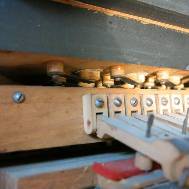 Photo 1 - Upside-Down Poppet Valves
The MELODY lever is, as you noted, spring loaded and to the right when not used. It operates, via a shaft, a slide valve (Photo 2) which switches two control lines between atmosphere (at rest) and two holes on the outer end of the tracker bar when the lever is operated. I do not think I understand this mechanism and have tried to draw the parts schematically. If what I have drawn is correct it looks to me as though the regulator pneumatics are bypassed when the melody lever is unused (the large valve beneath the pneumatic will be open allowing vacuum to flow to the stack without the conical valve controlled by the pneumatic to impede the flow. When the lever is operated the large internal valves will close allowing the regulators to operate (assuming the tracker holes are closed by the roll) except when a hole in the roll causes the valves to open and hence provides some louder emphasis. Could this be a form of Themodist mechanism? (I have of course only read of this and never seen one). I am troubled at the conclusion that the regulator pneumatics are effectively disabled unless the melody lever is held to the left, and perhaps I have drawn this incorrectly, but at present I can't see that I have. I attach my drawing of this mechanism and a few photos of the components involved.
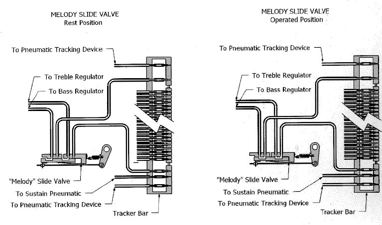 Trackerbar & Melody Switch Tubing Diagram 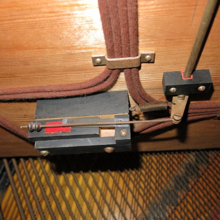 Photo 2 - Melody Lever & Switch
Photo 3 Three internal valves the lower is cut-out and the two upper control supply to the two regulator pneumatics.
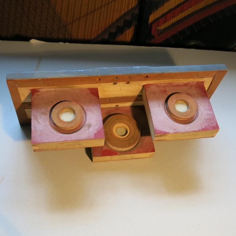 Photo 3 - Cut-Out and Regulator Valves
Photo 4 The outside of the valve assembly (Photo 3) with the manifold which attaches control lines to loudness pneumatics, vacuum cut-out and the two regulator primary valves. Bleeds for regulator primary valves and the cut-out valve can be seen.
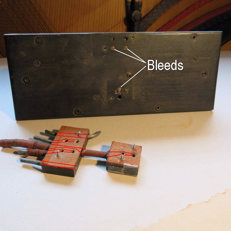 Photo 4 - Outside of Manifold for Cut-Out and Regulator Valves
Photo 5 Shows the main vacuum chamber with the valves removed, The primary valves for the two regulator valves are above and between the two regulator pneumatics. Internal channels transfer the primary output to the large secondary valves. The holes leading to these channels can be seen below the primary valve assembly.
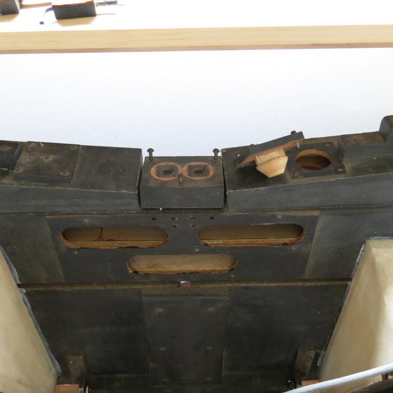 Photo 5 - Valves in Photo 3 fit into Slots in this picture
Photo 6 Shows the RH loudness valve and how it connects directly to the main vacuum chamber. (Notice it's location in relationship to the medium-size bellows -top left of picture. This is the same bellows that is seen in Photo 5 -top right w/conical-shaped valve removed.)
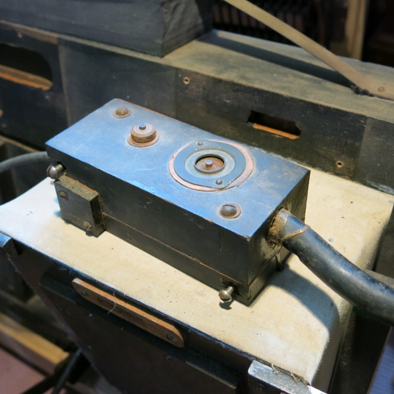 Photo 6 - Right-hand Side Loudness Valve
Photo 7 and Photo 8 Show the physical arrangement of the regulator pneumatics.
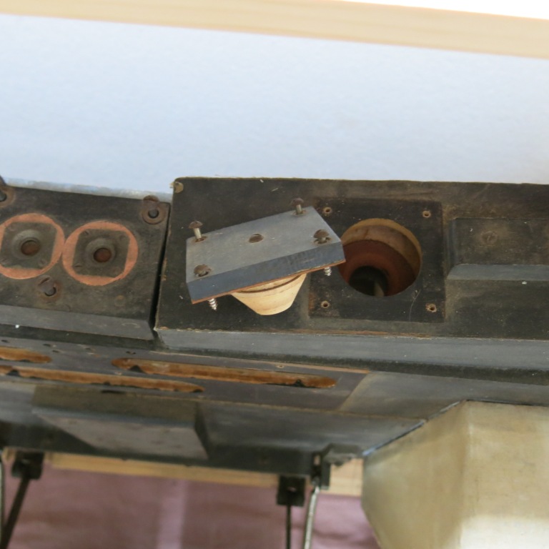 Photo 7 - Regulator bellows and Restrictor 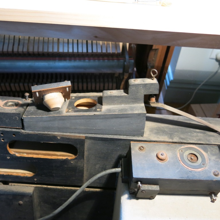 Photo 8 - Primary Valve and Pneumatic
Photo 9 and Photo 10 show the two ends of the tracker bar, The outermost small holes go to the tracking pneumatic, the large square hole at the left end goes (via a switch ) to the sustain pneumatic, and the two narrower slit like holes go via the melody slide valve to the two regulator mechanisms.
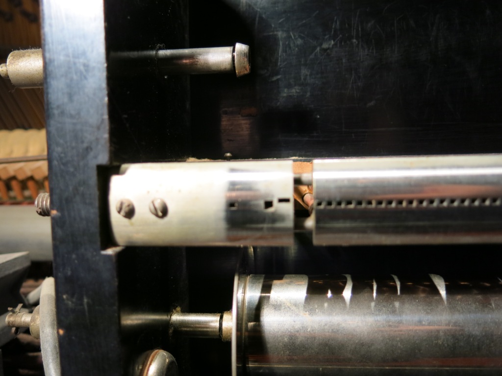 Photo 9 - Trackerbar Left Side 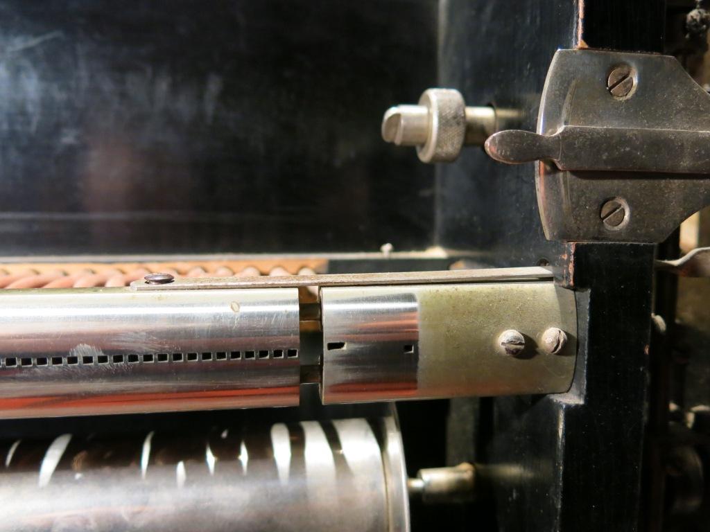 Photo 10 - Trackerbar Right Side I am sure this will be far more easily understood by you than me and would value any comment or correction of my thoughts you may have. Regards John Morris
John had previously sent some pictures which add a little more dimension to the player system. They are shown below with brief explanations.
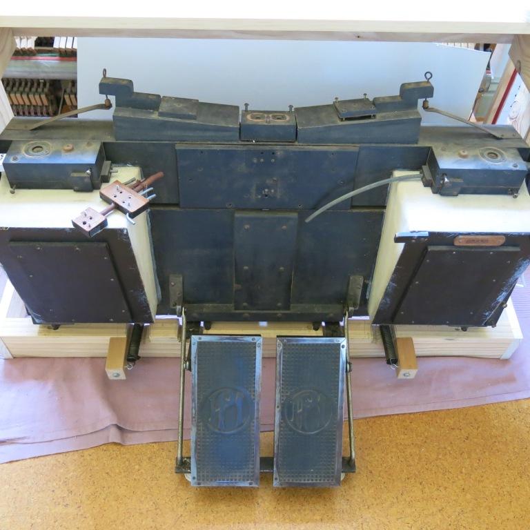 Exhauster Assembly with Reservoirs on the front side of the assembly. Also shows the orientation of the regulator valves and bellows. Exhauster bellows are on the back side of the assembly. The rationale for having three valves to operate one expression bellows is unclear. 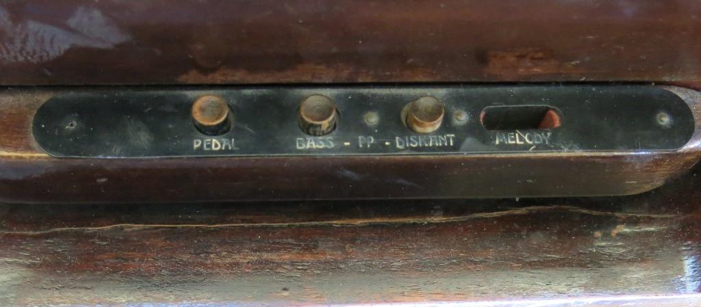 These are the operate controls in front of the keys. They might shed a little light on purpose for the three valves per expression bellow. Note the two buttons marked "Bass" and "Diskant" (or Treble). The "PP" between the buttons indicates that they are for decreasing the volume of the music. In fact, looking a little closer at the two valve boxes the are mounted to the left and right of the Expression bellows, note the size of the tubing (see Photo 6). Not look at the picture below. It is the Treble Soft Pneumatic. This pneumatic is connected via linkage to a secondary hammer rail (which is behind the regular hammer rail). It is known as a "Split-Rail" because it moves all of the hammers, from the middle of the keyboard to the highest note, closer to the strings. This effectively decreases the 'strike' (or blow) distance, which decreases the volume of the music. So, the "Bass" and "Diskant" Pushbuttons operate the Bass and Treble Soft Pneumatics. Therefore, they have nothing to do with the "Melody" lever or the Expression bellows. (One mystery solved.) 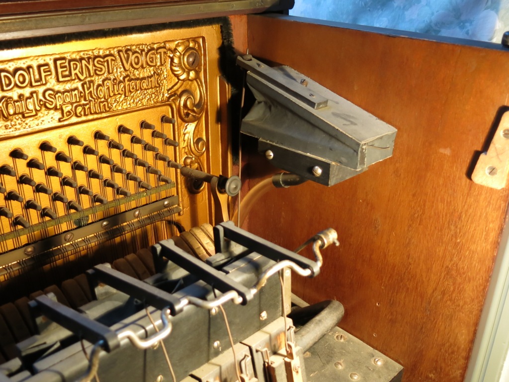 Treble Soft Pneumatic operates Split Hammer Rail to reduce the volume of the music. After examining all of these pictures at length, I'm still a little confused. What's confusing is the purpose of the two extra holes on the inside of the manifold board (see Photo 3) which are located to the left and right of the two center holes. Looking at the outside of the manifold board and the junction block that mounts on the board (see Photo 4), there are only two holes with the bleeds directly below each hole. This arrangement is mimicked with the cut-out block directly below with the exception that the bleed is above the hole instead of below the hole. Looking at Photo 5 we see the four holes on a row. So, the question is: What is the purpose of the two outside holes? Are there elbows or channels somewhere else on the manifold board that are not shown in any of the pictures? Now, what's also interesting to note is that on the junction block which mounts on the manifold, there are five tubes on the top of the block. However, the two outside tubes simply go through the block to elbows on the bottom side of the block. Those elbows get connected to the Bass and Treble Soft Control Valves. The two corresponding tubes on the top of the block get connected to the Bass and Treble Pushbuttons. So, this still leaves the mystery of why there are (apparently) two valves of each of the Expression bellows. And, another question that comes to mind is: Does activating the Expression Valves "increase" the volume of the music? If so, how is that accomplished? Without more information, one can only assume that the vacuum level is somehow clamped to a slightly lower level via the expression system. Then, when the Melody lever is activated, Theme perforations in the music roll are allowed to pass through the Melody switch, which triggers the expression valves. That would 'un-clamp' the system, which would "Accent" notes for the period of time that the Theme perforations are present. Lastly, after considering everything, I'm inclined to think that the Theme holes in the trackerbar are channelled through the Melody switch such that the holes in the trackerbar will allow a signal to pass through to the expression valves when the Melody switch is in the 'relaxed' position. If that's the case, then activating the Melody switch manually would allow the user to manually add accents to the music. |

![]() ..To
The Top of this Page . . . . . . . . . . .
..To
The Top of this Page . . . . . . . . . . . ![]() ..To The HOME Page
..To The HOME Page
|
Since "Player-Care" is an internet business, I prefer that we correspond via E-Mail (click here to fill out the 'Request Form'). However, if I'm not in the middle of some other activity, you can reach me at 732-840-8787. But please understand that during the hours from 8AM-5PM EST (Mon-Sat), I'm generally quite busy. So, I probably won't answer the phone. If you get the answering machine, please leave a detailed message stating the reason for your call. Also, repeat your name and phone number clearly and distinctly. By necessity, I prioritize everything in my life. And, if you call and just leave your name and number, and ask me to call you back, it might be a day or two before I return your call. Why? Because I don't know why you want me to call and I might not be prepared to assist you in an effective and efficient manner. If you leave me an E-Mail address (which I prefer), spell it out phonetically. The more you do to help me, the more I can help you in return. Don't rush. You have four minutes to record your message. |
|
407 19th Ave, Brick, NJ, 08724 Phone Number 732-840-8787 (Voicemail Only, No Texts) |
