|

|

|

|

|

|
| Home | Manuals | Supplies | Search | Consult | Contact | Testing | Service |
|
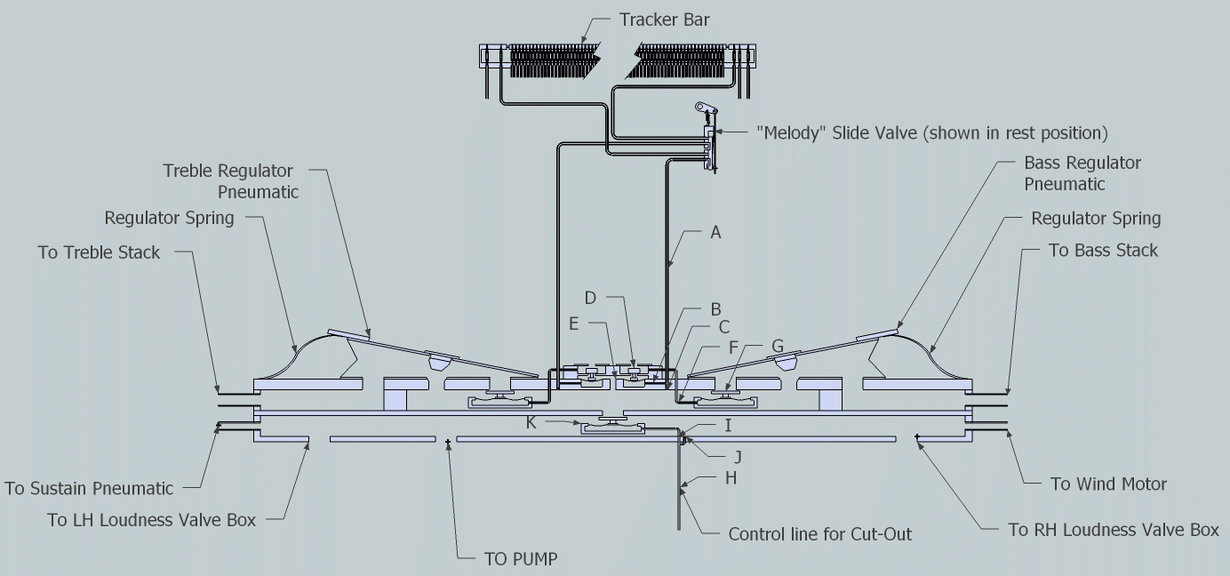
This is a continuation of my correspondence with John Morris in Australia concerning his Adolf Ernst Voigt Player Piano. In the interest of time, I have not edited the text that John submitted, but rather I have attempted to present the information in such a manner that it can be as easily understood as possible. Just below is another schematic diagram that John Morris created. It was sent to me in the PDF format and I converted it to a GIF format in an effort to prevent compression and the blurriness that often occurs when converting a PDF picture to a JPG format. To download the PDF file, click here.  Melody Switch and Expression Components - Labeled (Click Here to Enlarge) (Editor's Note: It took me awhile to figure out that the above image is drawn from the perspective of looking down at the device as though you are standing in back of the piano. If you were in front of the piano, the right hand side would be the treble side, and the left hand side would be the bass side. Not that it makes a whole lot of difference, but it can be somewhat confusing until you look at the diagram from the correct perspective.) I will try to answer the questions you posed, although I still do not think I understand how the "Melody" system works. First let me deal with the questions I can answer easily. To help describe where things connect I have labeled parts of my schematic (pdf) with letters A thru K which I will try to put in my description as I go. 1. The purpose of the two outside holes on the manifold board? (See Photo 3, Photo 4, and Photo 5) There are indeed channels (F) within the manifold board (and which cannot be seen at all) which run from those holes to the two regulator valves (G). I have marked the approximate path of these in white on photo-01. When the manifold board is in place these holes meet holes in the top edge of the main vacuum chamber, which in turn lead via small channels in the edge (which can be seen in photo 02 -showing the vacuum system with the upper part of the primary valves also removed) to vertical channels in the primary valve block leading to the upper chamber (D in the pdf) of the primary valves. These can be seen as the holes in the light coloured circles in photo 03. The larger hole in the centre of the pouch leather showing in photo 02 is the connection direct to the vacuum (E in the pdf). The other two holes (B in the pdf) lead to the chambers below the pouch leather, with the bleeds (C in the pdf) below leading directly into the vacuum. The hole in the cut-out block (I in the pdf) leads directly to the Cut Off valve for the stack vacuum (K in the pdf) and its bleed (J in the pdf) goes directly to vacuum. This bleed can be seen directly above the valve in photo-01. The control line for the cut out (H in pdf) comes, via the cut-out block and junction block directly from the governor and tempo control box. The nipple to which this line is attached can be seen in photo 04, photo 05 and photo 06. 2. Where are air motor governor and tempo control box and cut off for stack vacuum? These are located below the keyboard to the right of the pump unit as shown in photo 04. It connects to the unregulated vacuum, and feeds to the air motor through the rightmost pipe in the photo. The tempo control is the upper metal rod. The reverse control is the lower rod which passes through the device to operate the motor gearbox reverse. There is a control signal from this box to the cut-off valve for the stack vacuum. Exactly how this signal (which I think needs to be atmosphere to cut the stack vacuum) is achieved I am unsure). 3. Where are the valves for the automatic tracking device and where does it get its vacuum supply. The auto tracking device is shown on photo 07. The valves are located in the black block below the double pneumatic. This is shown, not very clearly, in photo 08 (I have not removed this device as I would prefer to leave its lead tubing I place if I can). The vacuum supply is via the larger twill covered led pipe shown in photo 08. Which can be seen in photo 07 and photo 09 going directly into the stack through the top cover.The three tubes seen in photo 09 going to the small manifold on the left side to be led to the lower part of the piano are the two expression signals from the tracker bar and the sustain signal from the tracker bar via an isolating switch. 4. Where is the auto sustain and where does it get its vacuum? The auto sustain device can be seen mounted below the keybed on the left of the piano in photo 10. It gets vacuum from the unregulated section of the main pump (opposite end to the air motor control) This device is shown in photo 11 and photo 12 and the vacuum connection and control signal connection can be seen. Valve is in the block below the pneumatic. The control signal comes from the tracker bar (photo 15) via an on off switch (photo 14 and photo 13) to the valve below the pneumatic. Lastly there is the question of how the 'Melody' expression system works. I agree with your description of how it should work with the tracker signals routed to the valves when the melody valve is in its relaxed position. This would be very like pictures I have seen of the Aeolian Pianola Themodist system (http://www.mmdigest.com/Tech/Themodist/themodistSchematic.html) and I think I understand what will happen. Unfortunately this doesn?t seem to be how my piano is put together. I think my diagram is properly reflective of what is here, i.e., the tracker signals rout to the expression valves when the switch is activated and there is atmosphere in the control lines to the valves when the switch is relaxed. This is, as you observed, the reverse of what seems sensible. I hope I am missing something, and this may become clear when I can re-assemble the piano and I can actually see what the signals are and how the valves react. This may be some little time as I have to replace much of the felt in the piano and need to re-cover a few of the pneumatics in the player section. I am hopeful that the main stack and the air motor will not need too much attention, but I guess that can only come clear as I progress. I hope the above is reasonably clear (and accurate). Thank you for your help to date. All the best John Morris
I want to express my sincere thanks to John Morris for all of the work he has done, and so graciously given to me, so that I can distribute it to the rest of the World. While we may never know who designed and built this player system, the fact that we have all of this information, and the accompanying pictures and diagrams, make it possible to have a clear understanding of the basic operating characteristics of the system. And, while we don't have (at this time) any of the exact specifications of the various parts, someone with a trained eye can look at many of the pictures and arrive at reasonable estimates with regards to things like the span of the bellows, the dish of the pouches, and the construction of various components.
In closing, if you have any more information about this player system that you would like to share with the World, please don't hesitate to write to me,
|

![]() ..To
The Top of this Page . . . . . . . . . . .
..To
The Top of this Page . . . . . . . . . . . ![]() ..To The HOME Page
..To The HOME Page
|
Since "Player-Care" is an internet business, I prefer that we correspond via E-Mail (click here to fill out the 'Request Form'). However, if I'm not in the middle of some other activity, you can reach me at 732-840-8787. But please understand that during the hours from 8AM-5PM EST (Mon-Sat), I'm generally quite busy. So, I probably won't answer the phone. If you get the answering machine, please leave a detailed message stating the reason for your call. Also, repeat your name and phone number clearly and distinctly. By necessity, I prioritize everything in my life. And, if you call and just leave your name and number, and ask me to call you back, it might be a day or two before I return your call. Why? Because I don't know why you want me to call and I might not be prepared to assist you in an effective and efficient manner. If you leave me an E-Mail address (which I prefer), spell it out phonetically. The more you do to help me, the more I can help you in return. Don't rush. You have four minutes to record your message. |
|
407 19th Ave, Brick, NJ, 08724 Phone Number 732-840-8787 (Voicemail Only, No Texts) |
