|

|

|
|
|
|
|
| Home | Manuals | Supplies | Search | Consult | Contact | Testing | Service |
|
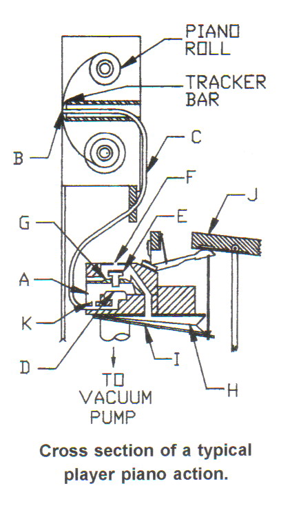
In this chapter I will explain the most important principle of operation which allows the player piano mechanism to operate. And while I fully admit that it is not the most important piece of information you will need to comprehend the player piano mechanism, it is singularly the most essential operating characteristic of the mechanism and must be completely understood. How do notes on a piano play when holes in a piece of paper pass over a set of holes in a metal or wooden bar full of tiny holes? First we should review a few basic facts of physical science. Our atmosphere exerts approximately 14.7 pounds per square inch of pressure on everything that exists at sea level. At higher altitudes the atmosphere exerts less pressure because the air is less dense. The effect of this pressure can be easily demonstrated by the action of inflating a rubber balloon. When air is blown into the balloon, the air pressure on the inside becomes greater than the air pressure on the outside. And, since the material the balloon is made of is flexible, it (the flexible material) has a natural tendency to move in the direction of least resistance, or lower air pressure, and the balloon inflates. When the opening at the top of the balloon is opened, the air inside the balloon, being at a higher pressure, escapes until the pressure inside the balloon is equalized. The point is: if a piece of flexible material is placed between two different atmospheric pressures, the material will try to move in the direction of least resistance. At one time or another almost everyone has sucked the air out of a
bottle, put their tongue over the hole and felt their tongue being sucked
into the bottle. That "sucking in" feeling is most commonly
referred to as a vacuum. A vacuum is described by
Webster's as "a space from which most, or all, of the air has been
removed". If an deflated balloon is placed inside of a bottle and then sealed
around the top There are many types of valves in every player piano. There are sliding valves, flap valves, pallet valves and poppet valves just to name a few, but it is the poppet valve and its associated parts that best demonstrates the above principle and how that principle is used to make notes play in a player piano. (1) An "air tight" chamber about the size of a book of matches
(1.5 inches by 1.5 inches by 0.75 inches) is created. Then a hole about the size of a
quarter is cut in the top and a flexible membrane is glued over that hole, like the
bottle and the balloon.
(2) A very small hole about the size of a pin, called the bleed (b, Fig 3), is drilled between the two chambers so that when air is " sucked out" of the upper chamber an equal amount will come out of the lower chamber. Then, because the vacuum, or negative air pressure, on both sides of the membrane is "equal", the membrane will not move at all. Next, the hole in the lower chamber (a, Fig 3) is cut so that it is six times larger than the bleed hole between the two chambers. It is important to note that it is the difference in the sizes of the bleed and tracker holes that set the stage for creating the differences in air pressure that are critical to the operation of the player piano (3) If the larger hole (a, Fig 3), or tracker hole as it is
properly called, is closed and a partial vacuum is applied to the
upper chamber, the vacuum on both sides of the membrane is equal and
the membrane does not move. However, when the partial vacuum exists
in the upper and lower chambers in equal amounts (due to the bleed)
and the "tracker hole" is opened to the outside
air, the air, being higher in pressure, rushes in and tries to "fill up"
, or balance, the vacuum in the lower chamber. And due to the fact that the
bleed between the upper and lower chambers is six times smaller than the
tracker hole, more air rushes into the lower chamber ( through the tracker
hole) than can be replaced by the bleed vacuum from the upper
chamber which maintains the imbalance for as long as the tracker hole
remains open. Furthermore, the flexible membrane reacts to the
imbalance and "puffs out" in the direction of the lower pressure,
or least resistance, towards the upper chamber. When the tracker hole is
once again closed, the vacuum from the upper chamber re-enters the lower
chamber through the bleed which balances the pressure and the membrane
returns to a relaxed state. This movement of the membrane, or pouch
as it is properly called, is like a switch that can be turned 'on' and
'off' by opening and closing the tracker hole. Also note (4) A third chamber is placed on top of the other two chambers (see Fig 5). In the top of the third chamber, a hole, a bit smaller than a dime, is cut in the center. This hole is called the exhaust port, but as you will see later, it is actually where air will enter into the valve assembly. Now another hole, slightly smaller than the hole in the top, is cut into the bottom of the third chamber (which is also the top of the second chamber) and is called the valve guide because it permits the valve stem to travel only up and down. (5) Another device is needed to cover and uncover the exhaust
port and valve guide or intake port. The device,
known as a valve The material the valve face is made of has to be able to create an "air- tight" seal around the holes in the tops of the second and third chambers. For many years, leather was the most popular and longest lasting material for making valve faces. Today the most common material is neoprene, which has thousands of tiny bubbles and is cut into disks about the size of a thick nickel. The exact thickness of the valve face is determined by the inside space between the exhaust port and the intake port minus 0.028" - 0.035" (slightly thicker than a paper match). This " extra space" is called the valve clearance and is the distance the valve moves from the "on" to the "off" position. The valve is installed in the valve assembly so that the bottom of the valve stem passes through the valve guide. Since the valve face is connected to the top of the valve stem, and is at least 30% bigger than the valve guide, the bottom of the stem comes to rest one sixteenths of an inch above the pouch when the pouch is relaxed, and completely closes the intake port, or valve guide hole. (6) When the tracker bar hole is "opened", the atmosphere, which is positive in comparison to the vacuum inside the chamber, rushes in to the underside of the pouch in an effort to " fill up" the vacuum. And since the bleed is six times smaller than the tracker bar hole, the atmosphere overcomes the vacuum and the pouch puffs up and pushes on the bottom of the valve stem causing it to move upwards thereby opening the intake port and closing the exhaust port. When this happens, the vacuum, which was only in the pouch chamber and the middle chamber, is allowed to enter the top chamber. (7) Finally, one last hole is cut into the top chamber
| |||
The Simple Explanation
For those interested in reading a more concise treatise of the principles of operation, read the series of articles by Wilberton Gould, which were written in 1927-1928 for the Tuners' Journal - click here.  E-Mail for John Tuttle E-Mail for John Tuttle |

![]() ..To
The Top of this Page . . . . . . . . . . .
..To
The Top of this Page . . . . . . . . . . . ![]() ..To The HOME Page
..To The HOME Page
|
Since "Player-Care" is an internet business, I prefer that we correspond via E-Mail (click here to fill out the 'Request Form'). However, if I'm not in the middle of some other activity, you can reach me at 732-840-8787. But please understand that during the hours from 8AM-5PM EST (Mon-Sat), I'm generally quite busy. So, I probably won't answer the phone. If you get the answering machine, please leave a detailed message stating the reason for your call. Also, repeat your name and phone number clearly and distinctly. By necessity, I prioritize everything in my life. And, if you call and just leave your name and number, and ask me to call you back, it might be a day or two before I return your call. Why? Because I don't know why you want me to call and I might not be prepared to assist you in an effective and efficient manner. If you leave me an E-Mail address (which I prefer), spell it out phonetically. The more you do to help me, the more I can help you in return. Don't rush. You have four minutes to record your message. |
|
407 19th Ave, Brick, NJ, 08724 Phone Number 732-840-8787 (Voicemail Only, No Texts) |