
|

|

|
|
|
|
|
| Home | Manuals | Supplies | Search | Consult | Contact | Testing | Service |
|
I have approached this treatise from the viewpoint that the reader has no working knowledge of vacuum-operated devices. For that reason, and in the interest of clarity, I purposely repeat myself a number of times. What I've attempted to do is start with the basics and build up on that foundation to the point where, by the end of the article, the reader will actually understand why the 4-hole tracker works. |
|
While it's important to know HOW something works, I believe it's equally, if not more important to understand WHY things work the way they do. Sadly, service manuals rarely tell the owner or the technician WHY a device works. So, in this treatise, I will explain the basic operating principles that allow the Standard Tracking Device to automatically track a music roll while the music is playing. However, before beginning you should turn your attention to the information about "How a Valve Works" -Click Here.
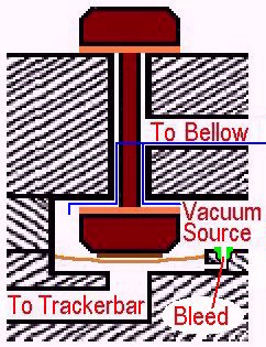
At the outset, one aspect of the Primary Valves in this device needs to be emphasized. The fact is that when a Primary Valve is "closed", or when it's in what would commonly be known as the "off" mode, vacuum is being applied to a bellow. As explained in the video, virtually all of the valves in a standard player piano only apply vacuum to a bellows when they are in the "on" mode, when a hole in the trackerbar is "opened". In this device, when a hole in the trackerbar is 'opened', the Primary Valve shuts off the vacuum being applied to its associated bellow. The importance of this peculiar operating characteristic will be fully explained in this treatise.
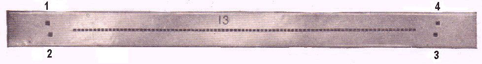
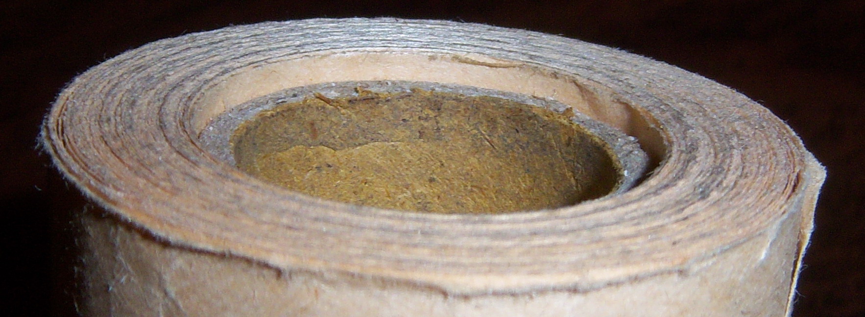
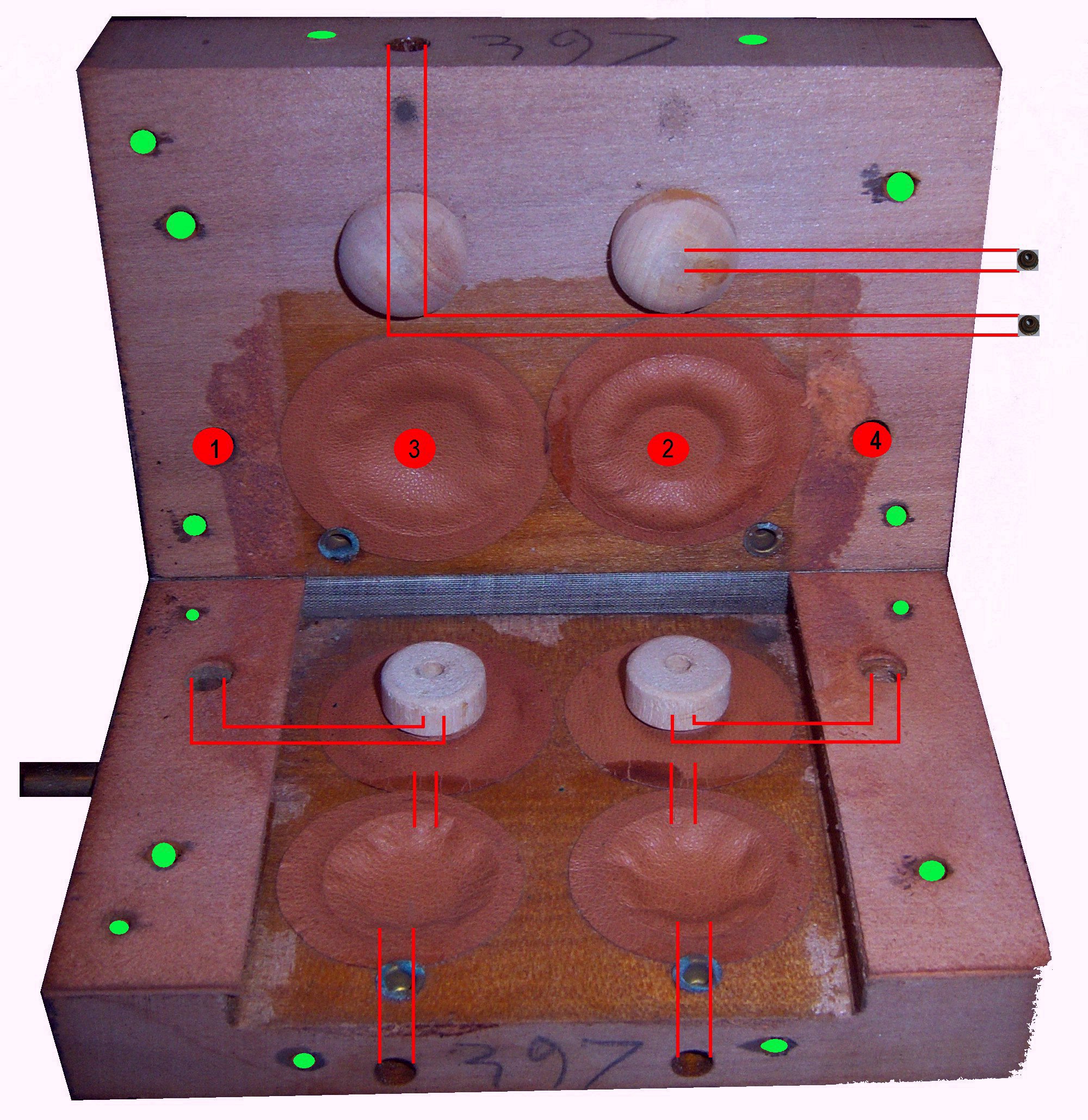
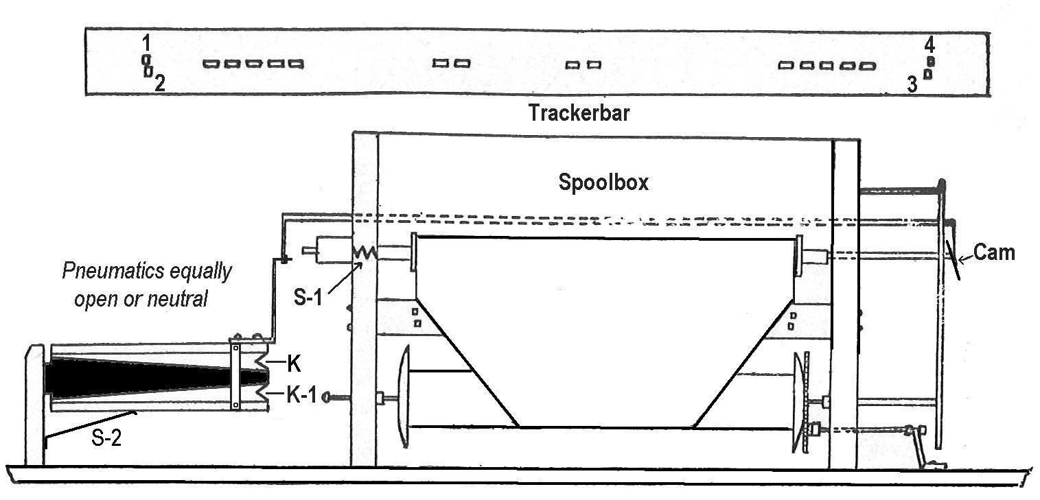 Referring to the above diagram, take note of the fact that when K closes further, the music roll will move to the LEFT. Conversely, when K-1 closes further, the music roll will move to the RIGHT. Also note that Spring S-1 is applying a constant pressure on the Cam via the music roll. So, as the Cam moves vertically up or down, the roll moves horizontally right or left, respectively. Further, note that the Spring S-2 is applying a constant upward pressure to the bellows assembly. Following the linkage which is attached to the assembly, we then see that S-2 is counteracting S-1. In fact, in a perfect world, these two springs apply an equal but opposite tension to the music roll such that if there is no vacuum in either K or K-1, the music roll will be perfectly centered between the two outer or inner tracking holes. This fact is important because during the Rewind cycle there is no vacuum applied to the tracking device. So, if there is an imbalance in these tensions, the roll will track to the left or right during rewind, and this could easily damage an older or brittle roll. (See Explanation 1 below) Lastly, take note of the position of the Cam when K and K-1 are open an equal amount. In terms of 'travel', it is 'centered'. This condition is known as the "Zero Set Point" or "Neutral" position. As a side note, Standard eliminated S-2 in the later years of production (about 1921-1926). Ultimately, this change was determined to be a mistake because systems without S-2 always favor moving the music roll to the right, and, during rewind, when there is no vacuum applied to the tracking system, the left edge of the music roll could get damaged. Also, without S-2 pushing up on the bellows assembly, the assembly has a tendency to fall down [because of gravity] such that K-1 is fully open and K is fully closed. As a result, over the years, the bellows cloth takes a 'set' in that position, causing a permanent imbalance in the system. However, the problem is avoidable (See Explanation 2 below). Ultimately, when Aeolian went back into production in the mid-1960's, a helper spring was added to the bellows assembly to counteract the tension of the spring in the left roll chuck, which helped keep the bellows in a balanced state during Rewind. In terms of understanding the operation of the shifter box, one of the critical aspects that's missing from every book and manual has to do with the location of the bleeds for four of the six pouches and the two bleeds (or what are sometimes referred to as "vents") for the shifter bellows. And, since they aren't even mentioned in the references, it's exceedingly difficult for a novice to comprehend 'what's happening inside the shifter box'. The picture below shows you all of the components that are inside of the shifter box, including the bleeds, along with a legend. Below that is a picture of the trackerbar with each of the tracker ports appropriately labeled. Note which of the ports on the trackerbar correspond to pouches in the shifter box: Port 1: Pouch B, Port 2: Pouch C, Port 3: Pouch A, and Port 4: Pouch D. The importance of why these ports and pouches are arranged in this manner will be explained later.
 Now, let's talk about the bleeds. First, the Large Bleeds (or "Vents") are located between the Shifter Box and the Shifter Bellows. Their purpose is to "restrict" the flow of air either into or out of their respective bellow. This is done to prevent the tracking device from reacting too suddenly to a change in the position of the music roll or an irregularity in the edge of the music roll. Second, the bleeds for the Primary Pouches (E & F) and the Secondary Pouches (A & C) are regular bleeds like those you would find in any regular note valve. As with all bleeds of this type, their primary purpose is to provide a path which allows the air (or atmosphere), which was used to inflate the pouch, to get sucked out of the pouch well after the signal port is closed, causing the pouch to relax and the valve to change state. Next, we turn our attention to the Secondary Valves, which are relatively unusual. While they are quite common in the Duo-Art Reproducing Player Action, I know of no other regular player mechanism that uses a pouch as a type of valve, which in turn is used to trigger the operation of a second pouch and valve. In the Duo-Art, this type of valve is called a "Cut-Out Valve", and it will be explained in detail shortly. Also, we have the four pouches which are labeled in Yellow; A, B, C, and D. Note that pouches A and B are situated such that they will interact with the Secondary Valve Button on the left while C and D will interact with the Secondary Valve Button on the right. This is the most unique aspect of the Standard 4-Hole Tracking Device, and to my knowledge no other device in a regular player piano uses two pouches to control the state of one valve. (In this paragraph, only Pouch B will be discussed. However, as can be seen in the picture, pouches B and D are identical in every respect. And while this information is very important, that importance might not be completely understood until after the discussion concerning the operation of the Secondary Valves.) Looking again at what is most commonly known as a 'cut-out valve', and in this case Pouch B, to the untrained eye it seems to be just a round piece of pouch leather that's glued around the perimeter of the pouch well such that it covers the hole in the raised area in the center of the well. If that were true, it would be difficult (if not impossible) for a sufficient amount of vacuum to pass under the leather and through the channel that leads to the tracker port on the trackerbar. However, such is NOT the case. In fact, the leather membrane actually has a slight 'upwards' dish which, upon close examination, is visible in the picture of the inside of the shifter box. This upwards dishing of the pouch membrane makes it quite easy for the vacuum and the atmosphere to pass 'through' pouch well B. In fact, the pouch only has to 'lift' (with virtually no effort) about 0.020" for a signal of sufficient strength to pass from the trackerbar to the Primary Pouch and activate the Primary Valve. As was seen in the video, the hole in the trackerbar only had to be open about 0.020" to trigger the Primary Valve into operation. This is possible because unlike a normal valve there is almost no force holding the membrane 'down' and almost no force is required to push the membrane 'up'. An extremely important fact to keep in mind when restoring the shifter box is the upwards dish of the pouch. If the dishing is too shallow, the Primary Valve will struggle to work when Ports 1 or 4 are open a slight amount -which it must do for the device to operate smartly. Conversely, if the dishing is too great, the natural resilience of the leather will make it difficult for the membrane to close the hole in the center of the pouch well when the opposing pouch (above the secondary valve button) tries to push the inflated pouch (to which the button is glued) downwards and turn the Primary Valve 'Off'.
(In this paragraph, only one of the two secondary valves will be discussed. However, as can be seen in the picture, they are identical in every respect.)
While it might not be very obvious, pouches A and B are not the same size. Pouch A is 1-1/2" in diameter and pouch B is 1-1/4" in diameter. But more importantly, pouch A has a 'working' diameter of 1-1/10" while pouch B has a 'working' diameter of 9/10". That being the case, and all other factors that effect the movement of a pouch being equal, pouch A will always be more powerful than pouch B simply because it's bigger. Also, although it might seem like a somewhat insignificant point, note that there is a wooden button glued to pouch B. That button (see below), along with the leather valve facing that's glued to the bottom of the button, weighs 0.6 grams. That weight, plus the force of gravity, further decreases the 'power' of pouch B, making it even easier for pouch A to overpower (or push 'down') pouch B. The point that is critical to understand is that regardless of the position of pouch B (inflated or neutral), pouch A will always push the button (and pouch A) down when it gets inflated even slightly, and that action will prevent the signal (or the atmosphere) entering Port 1, on the trackerbar, from ever reaching the Primary Pouch (E), and the Primary Valve will CLOSE. This point bears repeating. Since pouch A produces more power than pouch B, pouch A will push pouch B down and close off the signal to the primary pouch (E) even if pouch B is inflated. The importance of this fact will be seen later in this treatise. 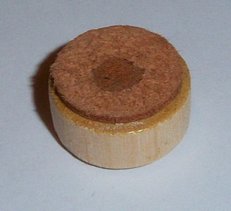 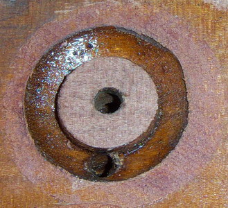
Referring back to the study about How Valves in a Player Piano Work, recall what was said about the 6:1 ratio which must exist between the size of the hole in the trackerbar and the size of the bleed in order for the valve to change state. (Just to clarify, the bleed does not have to exist in order to turn a valve 'On'. The bleed is needed to allow the pouch to deflate rapidly, which in turn allows the valve to return to the 'Off' position.) Now consider what would normally happen if the hole in the trackerbar were to remain open as little as 17%. If you figured out that the valve would never turn 'Off', you are correct. This is because the amount of air entering the pouch well will remain equal to or greater than the amount of air being sucked out of the pouch well via the bleed. And, until the amount of air being sucked out of the pouch well is greater than the amount of air entering the pouch well, the pouch will not relax enough for the valve to change state. However.... the poppet valves in the tracking device are not activated or deactivated in a conventional manner. Rather, the operation of each of the Primary (poppet) Valves is respectively controlled by two other pouches. As a result, the tracking holes only need to be open or closed 10%-15% of the way to operate the Primary Valve.
The point is that the slightest movement of the music roll left or right will turn a Primary valve 'On' or 'Off' position. It is never in an 'in-between' state. Now, with regards to the shifter box and these two primary valves, they are constantly shifting the position of the tracker bellows back and forth in an attempt to keep both of the outside (or inside) trackerbar holes open exactly the same amount. This primarily happens because of the Spring (S-1) is constantly trying to push the music roll to the RIGHT. Also, the outermost edges of the outside holes (Ports 1 and 4) are purposely set slightly further apart than 11-1/4", which is the standardized width of a music roll.
  As was explained earlier, due to the larger size of the pouches for the Secondary Valves, they will constrict or close off the air passageway for the signal coming from the outside tracker ports fairly easily. As a result, if an inside port is open only 15-20% it will shut off the signal to its associated Primary Valve 100%. Look again at the way the tracker holes are tubed to the trackerbar. Notice that Port 3, which is the inside port of the right side of the trackerbar, effects the operation of Secondary Valve on the LEFT or Port 1. And conversely, when Port 2 opens only 15%-20% it will shut off the signal from the outside POrt 4 on the RIGHT. So, what is going to happen? To fully understand how all of this effects the position of the music roll, we have to understand which way the music roll moves at each of the possible States of operation, and we have to reiterate the basic purpose for having an automatic tracking device. In the hope of trying to make the next section of this treatise a little easier to understand, two points need to be emphasized. One, only by closing a port is vacuum applied to a bellow. Two, the Secondary Valves cannot effect the position of their associated Primary Valve unless that Primary Valve has already been activated. It is for these reasons that Port 3 is associated with the operation of Port 1 and Port 2 is associated with the operation of Port 4. First, let's talk about what we're trying to accomplish with the device. Naturally, the purpose of the device is to keep the holes in the music roll aligned with the holes in the trackerbar. But more specifically, we want the device to move quickly back to the Zero (or center) position as soon as the music roll gets a little 'off track' to either the right or the left. So, if that's the case, we also need to know which direction the music roll is moving during each of the various States. Below is a chart which shows all of the possible States of Operation. In State One, an equal amount of vacuum is being applied to both bellows. As a result, the device stays stationary or 'centered'. (This is the 'Neutral' or 'Zero Set Point' state that was mentioned previously.) It doesn't move the paper at all. In State Two, Port 1 (on the left edge of the trackerbar) is opened to some degree. This means that the paper has moved to the right. So, the primary valve associated with Port 1 will open, which admits atmosphere into bellows K-1 (see graphic) which allows bellows K to collapse further. Remember, it was only collapsed half way when Ports 1 and 4 were both closed, and Port 4 is still closed. Therefore, the music roll is moved back to the LEFT because of the vacuum in bellows K. In State Three, when the outside Port 4 on the right opens and Port 1 on the left closes, the primary valve associated with Port 4 opens and the primary valve associated with Port 1 closes. Therefore, the music roll is moved back to the RIGHT because of the vacuum in bellows K-1. Makes perfect sense, right? Yes, it does. But what comes next can be confusing unless you bear in mind that it's VACUUM that's doing the work of moving the bellows back and forth and atmosphere that is allowing the work to be done. In State Four, Ports 1 and 4 are both open a small amount and there is atmosphere in both bellows. In this state, the slightest movement of the music roll to the left or right will cause an immediate reaction by applying vacuum to the appropriate bellows and the roll will move back to the center position. Moving on the State Five, we can rightly assume that the music roll has moved too far to the right, and since both Primary Valves are already open or "on", we have to find a way to turn "OFF" the Primary Valve that applies vacuum to the bellows that shifts the roll back to the left. Looking back at State Two, we find that opening Port 1 (which meant that the roll had moved too far to the right) allowed atmosphere to enter into K-1 and the roll moved Left. However, it did so because Port 4 was still closed. Remember, vacuum is only applied to a bellows when a port is closed. So, the only way to move the roll to the left is to 'close' the Primary Valve that applies vacuum to the bellows that shifts the roll to the left. That Primary Valve would be the one that's associated with Port 4. And, if you'll notice what's happening in State Two, you'll see that Port 4 is "closed". So, even though it is Port 2 (on the left end of the trackerbar) that opens, it is the 'opening' of that port which triggers the Secondary Valve that 'closes' the Primary Valve that's associated with Port 4. State Six is exactly the opposite of State Five. Port 3 opens, triggering the Secondary Valve associated with the Primary Valve that applies vacuum to the bellows that shifts the roll to the 'right'. State Seven is, for all intents and purposes, the same as State One. Vacuum is applied to both bellows and the roll is centered. However, the slightest movement of the roll to the left or right will trigger State Five or State Six. States Eight and Nine are explained in the video. They can only occur if there is a rip or tear in the music roll, or if the edge of the roll is badly damaged. However, because of the unique design of the 4-hole tracking system, the tracking device will not react if both of the holes on one side or the other are opened simultaneously.
Put as simply as possible, the tensions applied to the music roll by springs S-1 and S-2 are constantly trying to 'squeeze' the roll flanges inwards. Since the right roll flange is glued and/or stapled to the core of the music roll, it can't move. However, since the core of the music roll is almost always (over 98% of the time) narrower than the music paper and since the left flange is almost never (over 99% of the time) glued or stapled in place, it's possible to squeeze the left flange inwards to the point where the space between the two flanges is less than the width of the paper. (How to reduce the possibility of this happening is explained in detail in the article about Player Roll Care -click here.) This can, and often does happen at the end of the roll, just before the system is shifted into the Rewind mode. This is because there are only two or three layers of paper left on the roll and some music roll paper -especially old paper- doesn't have enough strength or resilience to withstand the pressures being exerted by the springs, and it 'collapses'. Now, the only thing that can 'force' the left flange outwards is the paper, and while newer paper is often capable of doing this, old paper isn't and the paper just starts ripping as it scrubs against the flange/s. As explained in the article, this problem is avoidable. However, if the spring tensions are out of balance, the roll will 'track' to either the left or right all the time during the Rewind cycle. So, even if the roll tracked correctly during the Play cycle, the paper will rub against the flange during the Rewind cycle. This causes the edges of the music roll to become 'curled', and that's a whole other problem when it comes to proper roll tracking. Unfortunately, curled edges are far too common even on new rolls that are being operated on a player that has a defective or unbalanced tracking system.
A fool-proof way to prevent the bellows from moving to an imbalanced state is to keep a music roll in place in the spoolbox at all times. I recommend just leaving the last roll you play for the day in the spoolbox. That way, the pressure being applied to the tracking cam via the spring in the left roll chuck prevents the tracking cam from moving. Also, if you were to remove the roll and replace it with either an empty roll or another roll, the pressure being applied to the cam linkage by either the bellows or the bellows spring (S-2) could cause the cam to move in the time it takes you to make the switch, defeating the purpose of leaving the roll in place. |

![]() ..To
The Top of this Page . . . . . . . . . . .
..To
The Top of this Page . . . . . . . . . . . ![]() ..To The HOME Page
..To The HOME Page
|
Since "Player-Care" is an internet business, I prefer that we correspond via E-Mail (click here to fill out the 'Request Form'). However, if I'm not in the middle of some other activity, you can reach me at 732-840-8787. But please understand that during the hours from 8AM-5PM EST (Mon-Sat), I'm generally quite busy. So, I probably won't answer the phone. If you get the answering machine, please leave a detailed message stating the reason for your call. Also, repeat your name and phone number clearly and distinctly. By necessity, I prioritize everything in my life. And, if you call and just leave your name and number, and ask me to call you back, it might be a day or two before I return your call. Why? Because I don't know why you want me to call and I might not be prepared to assist you in an effective and efficient manner. If you leave me an E-Mail address (which I prefer), spell it out phonetically. The more you do to help me, the more I can help you in return. Don't rush. You have four minutes to record your message. |
|
407 19th Ave, Brick, NJ, 08724 Phone Number 732-840-8787 (Voicemail Only, No Texts) |

 Now it starts getting a little more complicated. At the end of this article is a Table which lists all of the various 'States' (or combinations) that could possibly be encountered by the Shifter Box as a music roll is moving across the Trackerbar. Of these Nine States, the most common are State Two and State Three. However, to gain a complete understanding of WHY the Shifter Box works, knowing the principles that allow State One to function sets the stage for all of the other combinations. In State One, all four ports on the trackerbar are closed, and as a result all six pouches are in their neutral or relaxed position. What that means is that there is an equal force (or level) of vacuum on both sides of all six of the pouches. While this is fairly obvious with regards to pouches A, C, E, and F, it might not be so obvious with regards to pouches B & D. But, notice the 'invisible channels' that connect the pouch wells E to B and F to D. (Also, refer back to the paragraph about the operation/construction of the
 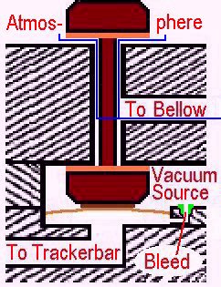 Again, when the vacuum level in both shifter (or tracker) bellows is equal, the bellows assembly (comprised of two opposing bellows -See
 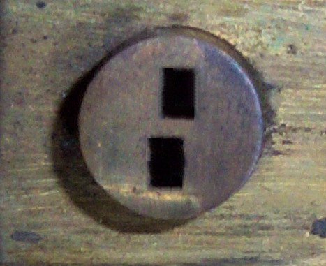 More precisely, the distance between the outside edge of the outside hole on the left and the inside edge of the outside hole on the right is exactly 11-1/4". The width of all of the tracker holes is exactly 0.058", which is just slightly less than 1/16". The point here is, if the music roll is exactly 11-1/4" wide, both of the outside tracker holes will be open about 1/32". And, as was explained previously, this is way more than enough to keep both Primary Valves 'On'. So, if the music roll moves as little as 1/32" in either direction, one of the two outside tracker holes will close and move the roll back to the center. If the music roll is slightly less than 11-1/4", then the onus falls on the Secondary Valves to keep the roll perfectly centered. This characteristic of tracking device allows for a nearly perfect balance in pressure between the two tracker bellows, and the slightest change in the position of the music roll is almost instantly detected by the pouches, which react to the change and keep the roll centered.