THE WELTE RECORDING SYSTEM
Preface by Craig Brougher

Hoffmann at the Welte-Mignon. Notice the long rectangular 'box' attached to the underside of the keybed. Gieseking at the Welte-Mignon. Notice the long rectangular 'box' attached to the underside of the keybed.
Note the long rectangular box underneath the keybed Can you identify the box with the two holes or the cabinet upon which it is placed? Who are these two men? Mr. Gieseking

The Welte Mignon system of recording performances for the T-100 "red" Welte roll format was a wonder of it's age. It was apparently developed in 1903 and was used extensively by Welte to record the great piano virtuosos of the age. The system allowed an artist great freedom, in that he was able to record any time he wished, and was able to hear his performance played back on the piano electrically; every note, all dynamics, and pedal nuances perfectly intact.

Many technicians and engineers have theorized for thousands of collective hours as to how such a feat could have been done at the beginning of the 20th century. Professor Ludwig Peetz, PhD, has researched the possibility of such a feat at this early stage and has recently demonstrated practically, historically, mathematically, and economically how it could have been done, taking cues from old advertisements, photos, and descriptions by observers, some of whom actually saw the instrument and handled a few replacement parts.

There may be those who still wish to deny that such a system existed and was not possible. There are egoists who still insist that the world is flat and will never agree that it is round regardless of the evidence. The majority of us however are willing to learn, and it should be no problem to listen fairly to the evidence with an open mind. We have duplicated the feat today digitally, but they did this analogically. Today's engineers don't know a whole lot about analog devices.

The scientific attitude toward discovery should not be, "They defrauded the public and just invented this story to look good." Instead, an engineer or physicist would say, "That's interesting. I don't see yet how they did it but I'll give it some thought, because they must have done so."

Getting downright practical about it, a lawyer would say, "A well-established reputable corporation like Welte, who invented the reproducing player piano, had everything to lose by involving their stable of artists in a fraudulent scheme which would certainly backfire in a class action conspiratorial lawsuit against them. They would have lost their business overnight with a claim that otherwise was not even necessary for their success." So if you appreciate good sense, ask yourself why risk everything to gain little or nothing? The stupidity is the accusation of fraud, not Welte advertisements, which not even their competition at the time doubted.

Welte was truthful about it, although they refused to give away even the slightest detail that might tip off their competition, and obviously disposed of their dynamic note sheets as soon as they had perforated a master copy, so as not to clue anyone in. An original section of a note sheet drawn by this machine nevertheless has recently been examined. This is an artifact. We know not only that they did it, but pretty much how they did it, too.

Corporate secrecy demands security even today when techniques are so well hidden that it would require an electron microscope to discover how something was done. The American company Wilcox and White Corporation which built the Artrio-Angelus also claimed to have a recording and playback system, as advertised in their own brochure entitled, "Genius Immortal." In the chapter "How Artrio-Angelus Records Are Made," we read about a recording piano connected by cable containing hundreds of wires, to an electric recording device. It in no way affected the piano's touch or response. The artist played, just as he would play on the concert stage, and could then hear his performance as a member of the audience, moments later.

As quoted from "Genius Immortal" for the Artrio-Angelus Reproducing Piano:

"And then the artist sits back and listens to the reproduction of his playing- listens as does the audience, without thought to the production of the composition- and in this regard a remarkable result has been achieved. For each time an artist plays a certain composition, he plays it with a slight difference. His mood, the temperature of the hall, any one of a thousand details may affect his playing. He finds that in certain passages he has not played it as he wished- as he actually thought he was playing it. Dissatisfied, he again seats himself at the piano- again his playing is faithfully recorded. "Ah!' he exclaims as he hears the reproduction- ‘That is what I meant'-- and when he is satisfied, and not until then, does he attest that master record with his signature."

It is not necessary to know exactly with certainty how it was done in detail. Only that the technology of the day made it quite possible to do this a number of different ways. False claims were not necessary, apparently.

Starting on January 28th, 2000, before I learned of Dr. Peetz, I wrote a series of articles for the MMD regarding one possible way that Welte might have built an electric recording and playback instrument, utilizing the technology of the day. As it turns out I wasn't far off. My articles, for the record, are numbers 2000.01.28.15, 2000.01.27.24, 2000.01.26.09, 2000.02.07.13, 2000.02.06.11, 2000.02.02.08, and 2000.01.29.14, in the MMD archives. One of the main differences between the simplistic drawing given of the mechanism and my keyboard sensors was that the sensing mechanism had an abstract action which allowed the una-corda soft pedal to slide the keys back and forth without taking the sensors with them.

One misleading detail was to infer that the sensor box under the keybed was a "trough of mercury." The box under the keybed was tapered like a trough for clearance, not to water horses. So the term "trough" is a descriptive adjective used as a noun, referring to its shape rather than its function. You will also see in Dr. Peetz' illustration that his mechanical configuration allows the sensor system to be abstract instead of connected directly to the keys. This is the only system that would allow the key frame to slide unimpeded for una-corda action.

The strongest misdirection to understanding the mechanical details of the sensor system is still due to an early oversimplified sketch which shows fine carbon rods dangling from the bottoms of piano keys into a trough full of mercury. One of the main reasons it would never work this way is that when a large grand is hammered by powerful pianists like Liszt for instance, the rhythm of the music, coupled with the power of the man's arms and wrists would shake the piano and even vibrate the stage it's on. This would set up waves in the mercury which, if the period was right, could even start sloshing, and 30 kg of mercury as shown, filling a 4 ft. long trough to a depth of 3 inches would not stop making waves anytime soon! Even baffles would be a waste of effort because of their own harmonics to the piano's tones. The piano's vibrations, transferred through the key bed would set up tiny waves which would be an appreciable percentage of the key depression displacement, ruining any dynamic sensing. The sketch was to correctly intimate the basic principle without giving away any of its mechanical details. This ambiguous scheme is common to depict unpatented, secret factory equipment required to explain a system.

We already know from first-hand reports that Welte used small carbon rods equivalent to 4H pencil leads. Mr. James D. Crank has already personally examined a box of these provided by Edwin Welte through Richard Simonton, a good friend. The method of sensing is not open to speculation. We know, very basically, what they used. When someone says "carbon," lights go on (or, maybe off) and immediately some may see images of carbon piles or granules, and pressure sensors. The trouble with these is that they do not register velocity directly but only a change in pressure. The frictionless C/Hg sensor is designed to measure vector amplitudes. Its output is described mathematically as the first derivative. Also the C/Hg sensor system requires no force- just displacement- whereas the carbon pile system requires compression. This wouldn't work directly under a key during a very light, quick strike in which the key doesn't even quite make it all the way to the front rail punching and is scaled for higher pressures than the lightest key impulses.

The idea of sensing by carbon rods (like pencil leads) in a row of tiny vials of mercury would prevent any kind of wave motion on the surface because of the high specific gravity (mass) versus surface area. The vials (more like sealed blown glass tubing) could hang in a cushioned rack and be very small, acting also as guides for the rods. The rod ends would be fitted or dip coated with a tiny insulative tip allowing them to float at zero resistance, automatically setting the rest position, or zero voltage position of each one. They would then be fitted at their top end with an adjustable abstract fixture to contact the key bottom. A fine wire braid with a silk center would make contact without mechanical friction. As the carbon rod assembly was bumped into the mercury by the key bottom, the level of the mercury displaced would rise around it, increasing its conductivity possibly by a factor of 4 times the normal key displacement. But even key action for quick staccato notes would propel the sensor into the mercury proportionally to the hammer blow. The key end would never have to even touch the felt to do that, and the tiny up-force provided by mercury flotation could not be sensed at the key because the key weights are many times more than that counter-force. So key impulse, strong enough to actuate a note would likewise actuate an equally fast sensor.

In this configuration, no spring is required and the depth of mercury displacement might be effectively multiplied by 4, giving the system greater electrical resolution in the same way that a lever changes a mechanical advantage. It's as if the key and its end travel were made 4 times longer from the balance rail. A carbon 2mm diameter. In a vial 2.236mm ID would cause mercury to rise 4 times as fast as it plunged down. By tapering the carbon, any rate including a reverse rate gradient could be generated. Still, it would have to be tested because mercury has a mind of its own. There is always a point of diminished returns beyond which any system will not work. The tiny vials could even tend to start functioning a tiny bit like thermometers, hence the flotation system self-compensates for expansion automatically.

One advantage however for a larger quantity of mercury in the box (but not filled up like a beer mug) would be to actually normalize heat gradient caused by the electric current of repeated notes. Mercury expansion therefore would be prevented in each vial, sinked away by a mercury heat sink in which the vials were immersed. This then would be a contact reservoir to which the vials were emptied and refilled.

What is so very interesting to me about professor Peetz' mathematical analysis is that since the compression of the front rail felt is about 3 mm depending on the power of the strike, that 3 mm is really all the rod needs to dip in order to resolve all dynamic levels by magnetic flux in the registering magnets except ppp, anyway, so he has made the system sensitive to 5 mm, total. He has shown that electrically, he can resolve everything from the lightest touch to the most powerful strike in 5 mm with sharpened soft rubber inkers, and since his system is also abstract from the piano's action, quick key action that will not touch the front rail felt will actuate the sensor as long as it actuates the hammer, just the same. So the vial idea isn't needed electrically except as guidance and higher resolution.

I invite you to read Dr. Peetz' MMD article now, understanding that refinements will suggest themselves. He is building an actual working model of his system as envisioned, from the sensor to the inker, in order to demonstrate the efficacy of the Welte system, using only their early technology. Below the MMD "teaser" is an earlier article sent to me personally by Dr. Peetz which goes into much greater detail for those interested. It might answer the technical questions which a general magazine overview could not.

Craig Brougher

*******************************************************************

"For The Record"

For the record, the only other dynamic record that we actually have proof of is from Dr. Clarence Hickman of Ampico Corporation in the middle '20s. He decided that the best place to pick off the dynamics of a piano was at the hammer shank. That is not because it was the only place to do it. It was primarily because he intended to measure the dynamic in relation to the speed of the hammer shank by measuring the time between two contacts as the shank passed. This was more convenient than measuring it at the key and was simply marked on paper passing a spiral high voltage wire on a rotating drum. A fine spark passed through the paper and was "developed" in dye water, later.

The Welte company it is believed, translated the key impulse force as a resistance. A lockout connection in series with it, as soon as the knuckle left the jack in the piano action, probably caused that resistance to be registered as a force by varying the width of an ink line on the paper note sheet. The dynamics are the same, the math is the same, and the relationship is one to one with hammer shank velocity, but key velocity and after-touch depression is from 5 to 8 times too fast and almost 50 times too close to measure with the Hickman spark chronograph.

For Dr. Hickman, the speed of the shank was easier to register with two marks through paper against a spiral wire spinning on a drum. The spacing between marks in a serial raster determined dynamics. For Welte, their version was an amplitude mark in parallel format and strictly analog. The Hickman recording horizontal line therefore was angled up from left to right across the note sheet, because the traveling spiral line (cursor) required a finite time to make one complete horizontal pass. This did not hurt its accuracy, since the editor's square lay at the same angle and the drum spun at a very high rate of speed. This system was used exclusively for all new Ampico B rolls coded by Ampico from the day it went into operation until some very late popular music was again hand-coded by Frank Milne reputably when Aeolian-American could no longer justify their roll editing department. So for all purposes, the spark chronograph was a highly accurate guide and indisputably successful, as all first hand accounts would indicate, but it would not allow a replay of the performance.

_____________&&&_______________

Below is a copy of Dr. Peetz' article concerning the physics of a recording system using carbon rods and a mercury trough. It is only sketched out and you may have questions about the details. The following is a physicist's view of the system. I have in my collection of e-mails the mathematics which document the likelihood that this system works as described, and works well.

Craig Brougher

_____________&&&_______________


Dr. Ludwig Peetz's Posting in
The Mechanical Music Digest


Subject: Welte-Mignon Recording Technology

 -- non-subscriber, please reply to sender and MMD --

There is no need of any speculation:

Most probably the Welte-Mignon T-100 recording system worked exactly
as Richard Simonton and Jim Crank described it (see, e.g., several
MMD contributions in January and February 2000):

Under each key a carbon rod was fixed by a spring.  The carbon rod
was dipping in mercury, the deeper the harder (and faster) the key
was depressed.  This resulted in a varying resistance and varying
electrical current: the deeper the key was depressed the higher
the current was, which acted on an electromagnet.  Forced by the
electromagnet, a sharp-edged rubber disk printed a line on a running
paper roll during the time when the key was depressed.  The harder
the key was depressed, the broader the line was.

Remember that after the Second World War Richard Simonton was well
befriended with Karl Bockisch and Edwin Welte, both the inventors
of the Welte-Mignon T-100 technology (see, e.g., MMD 2000.04.03 -
2000.04.06).  After the 1930s the T-100 recording system was of no
economical value any more, so it can be understood that the inventors
informed Dick Simonton about the once very secret T-100 technology.

Dick Simonton's friend, Jim Crank, confirmed that he was a proud owner
of some carbon rods, of some feet of an original recording roll with
lines of varying width, and a very old and poor photo of the mechanism
of the mastering machine and of the factory recording piano's trough
under the keyboard.  In addition, Jim Crank explained that the widening
of the lines was taken into account for the evaluation of the dynamics:
a slow key depression gave a gradual widening of the line, a hard key
stroke gave a rapid expansion of the line.

There is a proof that Welte worked with inked discs (or wheels) in
a writing system.  The American Welte Philharmonic Organ recording
system still exists in near-complete state in the Schweizerisches
Landesmuseum (Weiss-Stauffacher collection) at Seewen, Switzerland.
The corresponding Freiburg recording system, which worked somewhat
differently, is described by Kurt Binninger (a former Welte employee)
and published in "Organologica Acta", vol. 19, Berlin, 1987, pp.
179-207.  From the nice drawing on page 200 it can be seen that it
worked also with discs.

For one and a half years I've been working on the reconstruction of the
T-100 recording system strictly based on this historical description.
Recently (20th of September 2003) I presented my very encouraging
results during the annual meeting of the German mechanical music
society GSM in Triberg (Black Forest).  These results will be published
next year in the GSM Journal, "Das mechanische Musikinstrument".
I discussed a lot on this topic with Craig Brougher, Mark Reinhart,
Hans-Wilhelm Schmitz, and many other Welte-Mignon experts who provided
me important information, for which I thank them very much.

There is only one parameter which defines exactly the loudness of
a piano tone: the momentary key velocity at the HLP (HLP: hammer
let-off point), where the hammer leaves the lever in order to move
freely towards the string.  Nothing else!

I found the following points (by own experiments, theoretical
considerations and historical studies):

1.  Based on the historical piano dynamics recording system by Binet
and Courtier ("Recherches Graphiques sur la Musique", in "L'Annee
Psychologique", Paris 1896, available at the Freiburg University
library), an equivalent system to the later "seismographic"
Welte-Mignon-Licensee system was state of the art already in 1896.
Note that the Licensee system developed in USA in the 1920 and the
T-100 system developed 1901-1904 in Freiburg are completely different!

2.  If high quality and authenticity is requested, dynamic dependent
time delays must be taken into account for each tone during the
translation of the original recording roll of the production master
roll.  These time delays cannot be discriminated by systems which
record the dynamic information only summary for bass and treble.
Therefore -- on reason of accuracy -- the dynamics of each key must
be recorded separately, as Edwin Welte and Karl Bockisch did.

3.  The harder a piano key is depressed the deeper it goes into the
felt of the front rail punching.  There is a key distance travel
difference of nearly 3 mm between ff and pp tones.  The progressive
non-linear force-distance relationship is based on the elasticity of
the felt punching below the key.  The "constant key stroke hypothesis"
(see MMD 2000.02.04.07) clearly is wrong.

4.  The MHRM (minimum height of the repetition mechanism) must be taken
into account.  The best measuring condition is to write lines only in
the zone where the key is at or below this point.  In this case it can
easily be decided whether a tone is repeated (interruption of the line)
or held (continuous line).  The MHRM point is about 2 mm above the pp
and 5 mm above the ff key position, therefore the measurement range of
the mercury-carbon (Hg-C) sensor must be around 5 mm.

5.  Upon dipping the carbon rods into mercury, surface waves are
created which disturb the contact accuracy of the Hg-C sensor.  The
wave amplitude must be minimised by dipping the rod with its sharp edge
exactly perpendicular to the surface into the mercury.  Any rotation
or horizontal movement component gives rise to a much bigger amplitude.
Because the piano key moves in a rotational manner about the balance
rail fulcrum, a direct fixation of the rods at the keys is forbidden.
The only useful method is to transfer the vertical component of the
key movement with a well-guided prolongation device, e.g., a metal rod
moving a metal tube.  To ensure that the carbon rod follows exactly
the key movement, it must be pressed against the key by a spring.
Advantageously, the spring allows to transfer the current from the
moving carbon rod to a fixed point from which it can be transferred by
a connecting cable to the writing apparatus without any problem.  Such
a system fits exactly the description of Richard Simonton.

6.  In addition, the sharp edge of the carbon rods minimise spark
effects due to the inductance of the electromagnets: the conductivity
(inverse electrical resistance) and thus the current varies continuously
from zero to the maximum value.  To avoid oxidation effects (due to
dissolved metal impurities), a very pure grade of mercury has to be
used; following Simonton, the Hg surface was protected with an oil,
a very common technique in that time.

7.  A theoretical calculation of the electrical resistance of a
pyramidal edge of round section shows that it varies very sensitively
with the dipping height.  Special conditions regarding the resistance
of the connecting cables and the electromagnet can be chosen that the
conductance (and the current through the electromagnet) varies linearly
with the dipping height.

8.  This theoretical resistance calculation could experimentally be
proven by a small device using a normal pencil lead of 2 mm diameter.
If a 12-volt DC source is used a very high sensitivity of around 0.8
amperes per millimeter, within a range of 5 mm, can be achieved.
This Hg-C sensor, in the exact form as described by Richard Simonton
and confirmed by Jim Crank, can be used as a very sensitive analogous
key-travel measurement system.

9.  By experimental tests of elastic discs of different types (one
wheel with a round section of the elastic material and one with a
sharp-edged elastic part), I confirmed that the line width varies with
the force with which the wheel is pressed to the paper.  In both cases
there is a non-linear relationship between line width and force.

10.  By small modifications of the Welte Philharmonic Organ writing
system as described by Kurt Binninger, a very useful Welte-Mignon
T-100 recording system can be reconstructed.

11.  The momentary value of the key velocity is given by the first
derivative of the key-travel distance versus time.  With an analogous
key-travel measurement system, the momentary velocity value at the
hammer let-off point can be determined exactly (by graphical derivation
methods).  Other systems, like the Nystroem system or the Ampico-B
recording system, are only able to determine medium values by the
two-point [travel-time] method.  Medium values (which can easily be
determined with the above described system as well) take no account of
acceleration or slowing down effects which a pianist may perform within
the two-point measuring zone.

12.  Therefore the Welte-Mignon T-100 system must be regarded as the
principally best of all known dynamic recording systems.

Best regards to all Welte-Mignon friends!

Ludwig Peetz
Pirmasens, Germany

P.S: Within the next months I plan to build a one-key model of this type.

 [ Dr. Peetz teaches polymer and textile technology at the Pirmasens
 [ campus of Kaiserslautern College, and I believe he is also a master
 [ at chess!  ;-)  Danke sehr, Prof. Peetz, for contributing your
 [ technical article to MMD.  -- Robbie


Dr. Ludwig Peetz's Article Concerning
The Physics of the Welte Recording System


Ludwig Peetz Reconstruction of the Welte-Mignon T100 recording system technology p. 5

"Light touch: small line on then paper; hard key stroke, wider line. Slow key depression: gradual widening of the line hard key stroke, rapid expansion of the line.

Then some smart technicians at the Welte factory could interpret the loudness by not only the width of of the line but also the rate over of the line expanding."

Only with both parameters it is able to detect correctly, what I did with the piano: playing a pp-note and then pressing the key with maximum force as it would be a ff-note. The relevant position, where the hammer leaves the thrower to the string, is corresponding to a given position e.g. to a line width of 0,5 mm. At this point you will detect a small expanding rate, so you can verify, that it was a soft tone played, in spite of the fact that the slope then increases and the line width increases up to a high value of e.g. 3 mm, which corresponds to a very high force. Thus, only the combination of the two parameters position and velocity makes you sure what really happened!

5. Description of the Welte-Mignon Recording Process

Richard Simonton jr. cited his father from "In Search of Recorded treasures The Welte Master Roll adventure of 1948" /3/:

"There was a standard Steinway grand piano, equipped with a trough running the length of the keyboard and immediately under it. In this trough, there was a pool of mercury, and when the key was depressed, a carbon rod attached to the bottom of the key engaged the mercury and caused an electrical contact to be made. The resistance of this contact varied with the pressure exerted on the carbon rod so that actually , depending upon the blow with which the key was struck, there was a corresponding change in the electrical resistance of the contact made.

All of the keys were connected by wires to the recording machine with was usually some feet away from the controlling piano. This machine had within it the conventional rolls of paper which were entirely blank and without perforations, but were ruled their entire length with over 100 fine lines, each corresponding to the center line of its control mechanism. Above the point at which the impression actually took place on the paper was a series of small rubber rollers of a composition similar to the type used in a printing press, and these rollers were inked with an ink similar to that used in the printing industry."

There is another description by Ben Hall used with the permission of Mr. Richard C. Simonton /4/:

"The recording unit, connected to a Feurich grand piano in the Welte music hall, contained a roll of specially-aged, thin paper, marked off into 100 parallel lines. Poised over each line was a little wheel of extremely soft rubber, with pointed edges. Each wheel was in contact with an ink supply, and in this much of the process is resembled a small offset printing press. Under the keyboard of the recording piano was a trough filled with mercury; attached to the underside of each key was slim rod of carbon. As the key was depressed, the rod dipped into the mercury and an electrical contact was established between it and an electromagnet connected to the corresponding inked roller in the recording machine. The harder the artist hit the key of the piano, the deeper the carbon rod would plunge into the mercury, and the stronger the current between the rod and the electromagnet would be. The harder the inked rubber wheel was pressed against the moving paper roll, the wider the mark it printed on the paper. The pianist's pedaling and speed of attack was captured in the same way."

Both descriptions of the Welte-Mignon registration unit is very similar to that of Kurt Binninger's description /5/ of the Philharmonic Organ Registration System at Freiburg (see fig. 5). Kurt Binninger worked at Welte, Freiburg in the 1930's /6/.

In contrast to the Freiburg system the American organ registration machine (now in the Swiss museum in Seewen) worked with an indirect electrical-pneumatic lever system. In both organ recording systems metal disks have been used instead of rubber disks (because there is no need to register dynamics).

Ludwig Peetz Reconstruction of the Welte-Mignon T100 recording system technology p. 6
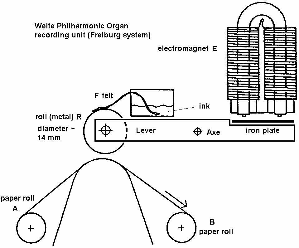
Fig. 5.: The Welte Philharmonic organ recording unit (Freiburg system; according to /5/)

6. Width of Lines printed by Elastic Disks

I investigated the line width / force behaviour of elastic disks with its originally round section and with a modified sharpened form (by sanding it manually). The disks have outer rings of rubber-like polyurethane (hardness: ~ shore 80 A) with following properties:

original sharpened

diameter: 50 mm 49 mm

thickness: 6 mm 4 mm

section: half circle triangle with an angle of approx. 75°

Disks sharpened to a lower angle (45°) couldn't be used because of folding problems when pressed against the paper.

The disks have been mounted in a roller system. For the tests a balance was used, with which I measured the force when running the inked disk on a paper (see fig. 6). An example of lines is shown in fig. 7. The line width as a function of force is given by fig 8 for both types of disks.
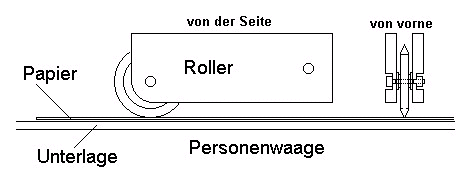
Fig. 6: Roller system used for printing on a paper using a balance (Personenwaage)

Ludwig Peetz Reconstruction of the Welte-Mignon T100 recording system technology p. 7

Fig. 7: Lines of different width using a roller with a sharpened disk at

around 0, 25, 50 and 75 N
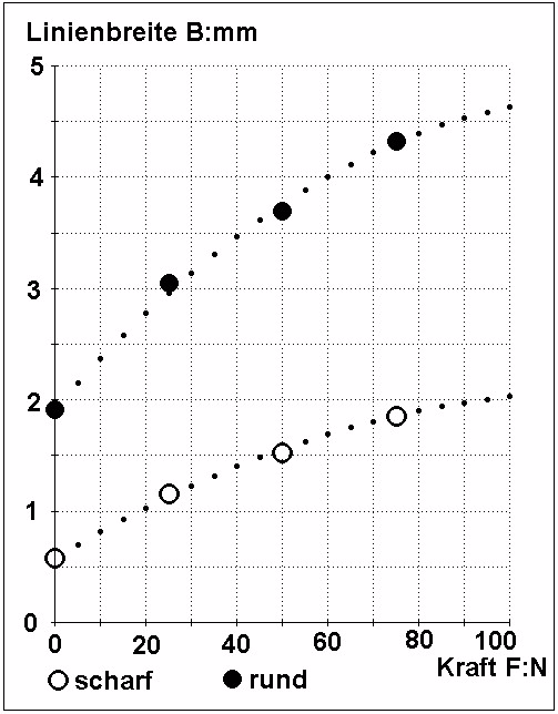
Fig. 8: Line width (Linienbreite B:mm) as a function of force (Kraft F:N) using a sharpened disk (scharf) and an original round disk (rund)

The line width data (± standard deviation) of Fig. 8 are given in the following table:

Force F:N Line width B:mm

round disk sharpened disk

0 1,91 ± 0,18 0,58 ± 0,12

25 3,05 ± 0,14 1,15 ± 0,14

50 3,70 ± 0,18 1,53 ± 0,12

75 4,34 ± 0,24 1,85 ± 0,12

Ludwig Peetz Reconstruction of the Welte-Mignon T100 recording system technology p. 8

Both types of disks show a non-linear degressive behaviour of the line width as a function of the force. The relative sensibility of the sharpened disk curve is higher as that of the original disk. Probably the width at zero force will be lower if more regular industrially produced sharp disks are used. It is clear that with softer disks there are higher gradients in the line width-force-curve.

7. Force / current relation of an electromagnet-iron plate combination

According to Coulomb's law the force F of an electromagnet pole exerted to an iron plate is proportional to p²/r² where p = / 0 is the magnetic pole force, the magnetic flux, 0 = 4 10-7 the magnetic field constant and r is the distance to the plate:

(10) F = a ² / r² (a > 0 constant)

As a first approximation p is proportional to the electrical current I through the electromagnet.

(11) F = b I² / r² (b > 0 constant)

But as known from magnetic hysteresis measurements, there are further phenomena which have to be taken into account:

(a) The remaining magnetisation of the iron plate and the iron core of the electromagnet giving

an additional linear contribution to the force with respect to the current I.

(b) The magnetic saturation effect, leading to a mean current exponent lower than 2 in the force

(c) If in fig. 5 the current I rises the electromagnet will attract the iron plate and the distance r will be

reduced

Therefore the relationship between force F and current I may complexly depend e.g. on current level, material composition and the form of the electromagnet and the plate.

Using the quadratic equation (11), the current I is proportional to the square root of the current I:

(12) (F:N)0,5 ~ I:A .

The corresponding relationship between Line width B and current I is given in Fig. 9, showing a progressive non-linear behaviour.
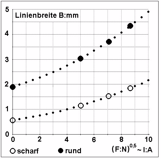
Fig: 9: Line width B:mm as a function of (F:N)0,5 which is proportional to the current I:A

Ludwig Peetz Reconstruction of the Welte-Mignon T100 recording system technology p. 9

8. How Piano Dynamics or the Loudness of a Tone has to be captured?

The principal question for the construction of a dynamic recording system is, how the dynamics of a piano (or the loudness of a tone) is created. Is this done by the force that the pianist exert to the key or by the velocity of the key?

There is a clear answer due to the working principle of the piano mechanics:

The only information needed is the momentary key velocity at one exactly defined key position, the point where the hammer is leaving the lever (hammer leaving point HLP). The key velocity at this point is strictly related to the hammer velocity hitting the string, and this velocity is related to the loudness of the tone. What happens after the key has crossed the HLP is of no importance to the hammer velocity. The hammer moves freely towards the string and its velocity cannot be influenced any more by enhancing or reducing the force executed on the piano key.

Therefore as the only reliable measure of a tone's loudness the velocity v0 at the HLP must be determined. This is the exact momentary velocity v0 = v(t0) given to the key by the pianist's finger at the time t0, when the hammer leaves the lever to the string. At this moment the key position is at the HLP h0 = h(t0) and the line width is B0 = B(t0).

An additional condition must be fulfilled to get a tone: v0 must exceed the well-defined minimum value vmin that ensures that the hammer gets more kinetic energy than the potential energy needed to reach the string.

9. Configuration of the Welte-Mignon recording system

It seems probably that at the Welte-Mignon recording grand piano the C-rods were connected directly to the key, but running in a guiding tube. There is a spring to press the rod against the key, that it has no degree of freedom. The rod just follows the key position directly (exactly spoken the projection of the key movement in the tube direction; the key varies in angle but the guiding tube doesn't: it must be fixed in a vertical position).

The felt has the function to slow down and stop the key (and the pianist's fingers) smoothly in a progressive force / way curve; otherwise it would take too much time to damp the movement down if heavy tones must be repeated very fast. The damping must begin after the hammer had left the lever to the string (otherwise the pianist wouldn't control as well the tones). This can be shown by fig. 2:

The force-way function of the felt and the piano match each other, if it is assumed, that the 0-point of the key position (with normal key position set to H = 10 mm) corresponds to a felt thickness of D = 4.94 mm. Since the HLP is at h0 = 1 mm it corresponds to a felt thickness of DHLP = 4,94 mm +1 mm = 5,94 mm, which is the practically the initial thickness of the felt (D = 6 mm).Therefore the felt and its non-linear force-way behaviour have no influence on the key velocity at the HLP and higher positions. However below the HLP the key velocity is slowed down by the felt. Therefore it is important to measure the key velocity in the felt-free zone above h0.

There is a next important point to consider:

In order to determinate whether a tone has been repeated or not it is necessary to measure, whether the key was over the minimum height of the repeating mechanism (MHRM), which is at h2 = 3 mm, or not.

If the key went over that point and then went down again, the tone was repeated and a new tone with its corresponding new loudness occurs. If the key doesn't reach the MHRM then the tone was simply hold (with no new loudness to determine apparently). To decide this, the MHRM must be included in the measurement system. The best way is to set the initial contact of the rubber disk to the paper exactly at the MHRM. In this configuration it can be decided easily whether a tone has been repeated or not:

If the key was above the MHRM limit and went down again then the line shortly interrupts, which shows that the tone was repeated. If the line didn't interrupt then the pianist had hold the tone (may be with lower force as he had used at the HLP).

It follows that in a reliable dynamic measurement system using Hg/C-contacts there is a difference in height between MHRM and HLP of about h = h2 - h0 = 2 mm, in which the key position must be measured.

Ludwig Peetz Reconstruction of the Welte-Mignon T100 recording system technology p. 10

10. Determination of the exact value of v0 by a graphical tangent analysis

From the experimental data it seems clear that the function B(h) and its inverse function h(B) are non-linear. A graphical tangent analysis based on a differential calculus is a method known in the 19th century /7/ with which it is possible to determine accurately the momentary velocity v0 under non-linear conditions.

The non-linear functions B(h) and its inverse function h(B) can be determined experimentally by measuring the line with at different key height positions:
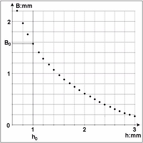
Fig. 10: Arbitrary non-linear line width function B(h) (example)
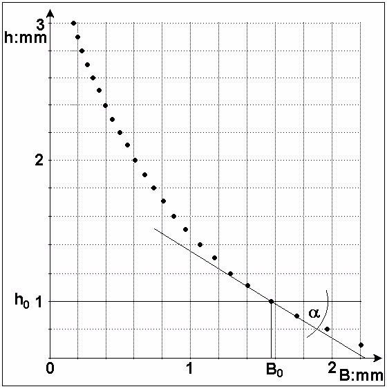
Fig. 11: Inverse function of fig. 10 h(B) with h'(B0) = tan

Ludwig Peetz Reconstruction of the Welte-Mignon T100 recording system technology p. 10

Fig. 10 and Fig. 11 show an arbitrary example of a non-linear line-width function B(h) and its inverse function h(B) including the HLP-values h0 and B0 respectively. From fig. 11 the first derivation

(13) h'(B0) = tan()

can be determined by the drawing the tangent to the h(B) at B0 (see fig. 11). The angle as well as tan() have negative values.

The dependence of the key position on time can be described by a chain of the functions h(B) and B(t):

(14) h(t) = h(B(t)).

The momentary key velocity at t0 is given by the first derivation of the key position with respect to the time

(15) v0 = v(t0) = - h'(t0)

The negative sign is chosen to define v0 as a positive value. Using the differentiation rule for chain functions it follows

(16) v0 = - h'(t0) = - h'(B0 ) B'(t0) = - tan() B'(t0)

The time dependent line width B(t) is a chain function of the varying line-width B(L) printed to the length L of the paper and the varying length L(t) of the printing position on the paper with time t:

(17) B(t) = B(L(t)).

The differentiation rule for chain functions leads to

(18) B'(t0) = B'(L0) L'(t0)

where

(19) L0 = L(t0)

is the paper length at the time t0, when the hammer leaves the lever and

(20) L'(t0) = vp

is the paper velocity vP at t0. Thus the momentary velocity v0 is given by

(21) v0 = - vP tan() B'(L0)
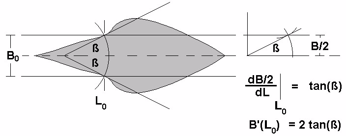
Fig. 12: Determination of L0 and B'(L0) from a printed line by a graphical analysis

Fig. 12 demonstrates how L0 and B'(L0) can be determined form a printed line by a graphical analysis. The form of the line is very non-linear in an exaggerated manner. The non-linearity is due to any acceleration or slowing-down effects exerted by the pianist to the key between MHRM and HLP (which might be thought in this example as a very artificial play) and the non-linearity of the functions B(h) and h(B).

L0 is given by the intersection of the line with two symmetrically centred parallel lines representing the line-width B0 which corresponds to the HLP.

Ludwig Peetz Reconstruction of the Welte-Mignon T100 recording system technology p. 11

At the two intersection points at L0 tangents were drawn which form an angle 2ß. The value tan(ß) corresponds to the first derivation of the half line-width B/2. Therefore it follows:

(22) B'(L0) = 2 tan(ß)

and the final result:

(23) v0 = - 2 vp tan() tan(ß).

Fig. 13 shows two arbitrary lines; in the case (a) there is no interruption of the line; therefore the key has not been above the MHRM, only one note has been played; in the case (b) the interruption of the line demonstrate that the key was over the MHRM, so that the note has been repeated with its own v0

determined by L0(2) and ß(2)
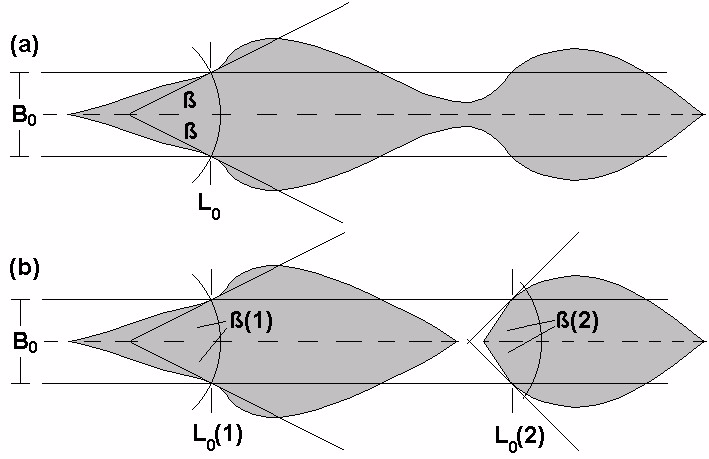
Fig. 13: (a) Only one note played without line interruption

(b) Two notes played with interruption

The question of the accuracy of this measurement system is a delicate one. Following Richard Simonton the registration paper was a standard roll of 328 mm width, entirely blank with over 100 fine lines. Such rolls are well-known /8/. There are even red perforated rolls which are equipped with lines on the entire length. I possess an example of No. 401 Consolation No. 3 Fr. Liszt, played by Ernst von Dohnanyi recorded the 13.IX.05, with 102 lines on the entire length. Since the separation of the lines is 3.2 mm the maximum line width is limited to the order of 3 mm.

For a high accuracy a measuring microscope could be used. End of the 19th century the accuracy of such equipment was up to 0,001 mm = 1m using glass plates with diamond-engraved grids /9/. Even mechanical screw micrometers reached that accuracy /10/, /11/. Furthermore it should be noted that the accuracy of angle measurements by standard sextants with nonius scale was 20" = 1/180° /12/. The basic accuracy can be enhanced by taking mean values of many measurements. In terms of reproducibility a standard deviation of the mean values of ß of than lower than 20" could be reached. It's only a question of statistics, the more measurements the better is the accuracy. However there is a bigger problem: the absolute accuracy. The piano mechanism and the Hg/C-contacts and the disks registration system must be adjusted for each key in the same way. It can be assumed that an absolute accuracy of a few percent could be reached at best. In this case a sophisticated measuring method which takes a long time for each note is only of theoretical interest.

A more practical easy and fast evaluation system can be constructed using a glass goniometer with 5 diamond-engraved parallel lines with distance B0/2 under a magnifying glass:

Ludwig Peetz Reconstruction of the Welte-Mignon T100 recording system technology p. 12
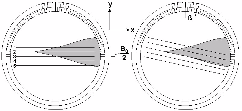
Fig. 14: Goniometer used under a magnifying glass for easy and fast determination of ß

The goniometer is connected to a paper rolling device were the paper position in x-direction (Length L) is measured separately. The goniometer itself can be displaced in y-direction, so that its line 2 is set parallel to the base line of the regarded note. Then the paper is displaced in x-direction until the lines 1 and 3 fit the line width. The goniometer has to be turned until the line 3 is the tangent of the curve at the rotational axe. The angle ß can be read accurately by a nonius scale. The opposite value of ß is measured in the same manner using the lines 3 and 5 with the base line of the note centred to line 4. Finally there will be a list of all notes of a registered music piece with its two ß values from which a mean value is taken. By equation (23) the momentary key velocity v0 at HLP can be calculated.

Since the times of Newton it is known that the momentary velocity is defined by the differentiation of the way with respect to time. Therefore a correct evaluation must involve a differentiation process. The easiest way to differentiate a curve in the 19th century was a graphical tangent analysis. Another way to get an even better (more objective) approximation of h'(B0) would involve a Taylor development of h(B) around B0

(24) h(B) = H(B0) + h'(B0) (B- B0) + h''(B0) (B- B0)² / 2 + ... + h(n)(B0) (B- B0)n / n!

to the desired degree n of non-linearity and a least squares fit according to Gauss using a huge number of data points in the vicinity of B0. This leads to the best approximation value of h'(B0) = tan() with respect to the data set but implies a considerable mathematical calculus effort. Since h'(B0) must be determined only one time this effort may be justified. A similar evaluation is possible in the case of B'(L0) = 2 tan(ß) but for each note the calculus effort is to high in a practical application.

There are many other ways to get more or less reliable approximated values of v0. The simplest way is a two point calculation of the mean velocity <v0>. This method was e.g. used in Nyström's Melograph in 1911 /13/ and in the AMPICO B- spark-chronograph system developed in 1929 /14/. It has to be noted that the mean velocity calculation neglects all acceleration and slowing down effects exerted by the pianist on the key.

In the Welte-Mignon-Hg/C-elastic disk recording system the mean velocity between the MHRM with height h2 and the HLP with height h0 can be determined by measuring the length of the line from its beginning at the paper length L2 to L0 at HLP. With the definitions

(25) h = h0 - h2 (negative value)

(26) L = L0 - L2 (positive value)

and the calculation of the time difference

(27) t = L / vP

it follows:

(25) <v0> = - h / t = - vP h / L

Ludwig Peetz Reconstruction of the Welte-Mignon T100 recording system technology p. 13

Any other pair of points i and j near the HLP with heights hi and hj can be used in the same manner. This evaluation takes into account the non-linearity of the B(h) curve but not that of the pianist's play.

Additional points can be introduced to get information on the pianist's acceleration (or slowing down) effects; e.g. by 3 points the mean acceleration <a0> can be taken into account. As well it is possible to use an empirical correlation between maximum line width Bmax, <v0> and <a0> to improve accuracy. However the graphical tangent method clearly is the best evaluation method because it delivers directly the momentary velocity v0.


CREDITS & REFERENCES USED IN DR. PEETZ'S ARTICLE


/1/ A. Binet, J. Courtier, Recherches Graphiques sur la Musique, in: L'Année psychologique, 2e année - 1895, p. 201-222, Alcan, Paris (1896).

/2/ Johann Friedrich Unger: Entwurf einer Maschine, wodurch alles was auf dem Clavier gespielt wird, sich von selbst in Noten setzt (1745, 1752, 1774); article by Jürgen Hocker in DMM 26, Sept. 82, p. 14-16 and DMM 27, March 1983, p. 21

/3/ Richard Simonton jr., MMD 2000.01.28®13

/4/ Ben M. Hall, „How is it possible? - The Welte Technique explained -" in Q. David Bowers; Encyclopedia of Automatic Musical Instruments, Vestal Press, Vestal, New York 1972 p. 327

/5/ Kurt Binninger, Die Welte-Philharmonie-Orgel,

/6/ Information by Hans. W. Schmitz, Stuttgart (he drawed the original of fig. 5 in Binninger's article)

/7/ Brockhaus Konversations-Lexikon 17. Auflage 1894 no. 5 p. 298-299 (Differentialrechnung)

/8/ There are several examples in the Edwin Welte heritage used for the transformation from T100 to T98 system (see Gerhard Dangel-Reese: MMD 2000.02.09®11)

/9/ Brockhaus Konversations-Lexikon 17. Auflage 1894 no. 11 p. 871 (Mikrometer)

/10/ Brockhaus Konversations-Lexikon 17. Auflage 1894 no. 11 p. 871-872 (Mikrometerschraube)

/11/ Brockhaus Konversations-Lexikon 17. Auflage 1894 no. 5 p. 299 (Differentialschraube)

/12/ Brockhaus Konversations-Lexikon 17. Auflage 1895 no. 14 p. 896-897 (Sextant)

/13/ Peter Hagmann, Das Welte-Mignon-Klavier, die Welte-Philharmonie-Orgel und die Anfänge der Reproduktion von Musik, Verlag Peter Lang , Bern, Frankfurt, New York 1984; p. 69-71

Note: the full text can be obtained by http://freidok.uni-freiburg.de/volltexte/608/ (File: hagmann.pdf 2082 KB); see also: Gerhard Dangel, „Das Welte-Mignon-Klavier" by Peter Hagmann, MMD 2003.01.09 ® 03 und Robbie Rhodes, Contents of „Das Welte-Mignon-Klavier" by Peter Hagmann, MMD 2003.01.09 ® 04

/14/ Peter Hagmann, Das Welte-Mignon-Klavier, die Welte-Philharmonie-Orgel und die Anfänge der Reproduktion von Musik, Verlag Peter Lang , Bern, Frankfurt, New York 1984; p. 71-76.

*******************************************************************

Written Permission from Robbie Rhodes,
The Mechanical Music Digest Editor

*******************************************************************
Date: Fri, 03 Oct 2003 03:31:52 -0700
To: "John A. Tuttle",
        Craig Brougher 
From: MMD Editor - Robbie Rhodes
Subject: Permission to republish article by Ludwig Peetz
Cc: Ludwig Peetz ,
In-Reply-To: <6.0.0.22.1.20031002104305.0406a240@mail.monmouth.com>
Mime-Version: 1.0
Content-Type: text/plain; charset="iso-8859-1"
Content-Transfer-Encoding: 8bit
X-UIDL: $SO"!gDh!!bCS"!\PZ"!
Status: RO

Dear John and Craig,

I am happy to grant permission to you to re-publish the article by 
Prof. Dr. Peetz at your web site.  It would be kind of you to mention 
that his article was first published in Mechanical Music Digest of 
27 September, 2003.

Mr. Berhard Haeberle of GSM sent the information following about how 
to purchase the book containing the interview, and he also offers 
his understanding of the efforts of Prof. Peetz.  The translation 
to English is mine.

Best regards,

Robbie Rhodes  
Mechanical Music Digest
http://www.mmdigest.com/Archives/

 - - -

Lieber Robbie,

soweit ich Prof. Dr. Peetz verstanden habe, behauptet er nicht, dass es
so gewesen sei, wie es Dick Simonton schreibt, er untersucht vielmehr
auf wissenschaftlicher Basis, ob das beschriebene Verfahren technisch
möglich ist. 

Auf alle Fälle wird voraussichtlich in DMM Heft 89 der Vortrag von Prof.
Dr. Peetz erscheinen.

"Acta Organologica" ist das Jahrbuch der Gesellschaft der Orgelfreunde.
Der Beitrag vom ehemaligen Welte-Mitarbeiter und späteren Erzbischöfl.
Musikdirektor († 18.7.1988 im 80. Lebensjahr) Kurt Binninger heißt "Die
Welte-Philharmonie-Orgel" und erschien in Vol. 19, Berlin - Kassel 1987
(ISBN 3-87537-227-1), pp. 179-207. Das Buch ist zu beziehen über die

Geschaeftsstelle der Orgelfreunde
Herr Roland Behrens
Josefstrasse 8

D-66693 Mettlach
E-Mail: gdobehrens@t-online.de

Herr Behrens kann dir bestimmt per E-Mail Infos über Preis,
Versandkosten und Bezahlungsmöglichkeit geben.

Gruß Bernhard

 - - -

As far as I understood Prof. Dr. Peetz, he doesn't claim that
[the technique used] was indeed as described by Dick Simonton; rather,
he examines the scientific basis for whether the described procedure
is technically possible.

In any event, the lecture by Prof. Dr. Peetz [presented at the GSM
annual meeting in Triburg, Sept. 2003] will probably appear in DMM 
journal 89. 

"Acta Organologica" is the yearbook of the Gesellschaft der Orgelfreunde, 
[Society of the Friends of the Organ].  The contribution by the former 
Welte employee, and later Archbishop Music Director, Kurt Binninger 
(who died 18.7.1988 in the 80th year of life) is called 
"Die Welte-Philharmonie-Orgel" and it appeared in Vol. 19 of
"Acta Organologica", published by Berlin - Kassel, 1987 
(ISBN 3-87537-227-1), pp. 179-207.  The book can be be obtained from
the office of the society:

Geschaeftsstelle der Orgelfreunde
Herr Roland Behrens
Josefstrasse 8
D-66693 Mettlach
E-Mail: gdobehrens@t-online.de
  
Mister Behrens can give you information via e-mail about price, 
shipping expenses and payment method.

 = = =

Some of the articles mentioned above, or portions of those articles, first appeared in the Mechanical Music Digest, and are used herein with the express permission of the authors and editors listed. All references are copyrighted and cannot be used for any purpose without the express written permission of the authors and the editors. Other references used in Dr. Peetz's treatise are similarly copyrighted and cannot be used without permission.

Home Manuals Supplies Search Consult Contact Testing Service

This page was last revised on March 11, 2019

Page Design by Player-Care
Webmaster-Questions/Suggestions

Since "Player-Care" is an internet business, I prefer that we correspond via E-Mail (click here to fill out the 'Request Form'). However, if I'm not in the middle of some other activity, you can reach me at 732-840-8787. But please understand that during the hours from 8AM-5PM EST (Mon-Sat), I'm generally quite busy. So, I probably won't answer the phone. If you get the answering machine, please leave a detailed message stating the reason for your call. Also, repeat your name and phone number clearly and distinctly. By necessity, I prioritize everything in my life. And, if you call and just leave your name and number, and ask me to call you back, it might be a day or two before I return your call. Why? Because I don't know why you want me to call and I might not be prepared to assist you in an effective and efficient manner. If you leave me an E-Mail address (which I prefer), spell it out phonetically. The more you do to help me, the more I can help you in return. Don't rush. You have four minutes to record your message.

Grand 16 IconGrand 32 Icon

407 19th Ave, Brick, NJ, 08724
Upright 32 IconUpright 16 Icon

Google Adsense Ad

SSL Certificates