
|

|

|
|
|
|
|
| Home | Manuals | Supplies | Search | Consult | Contact | Testing | Service |
Technola/Metrograde Player SystemIn late 2022, Loren Steyer from Alberta, Canada, contacted me to get some supplies for a player he was restoring. It soon became obvious that while the system was manufactured by AEolian, it was different from any of their other systems. Over the next six months, and with Loren's help, I began documenting the system with the hope of creating useful information for other owners and player technicians. By May 30, 2023, I had enough information to create this web page. In it, I hope to present everything I've learned about the system. Below is the Tubing Diagram of the system, which also identifies all of the components in the system. You can click on the diagram to see the full size diagram and save it to your computer. Below that you will find a number of pictures of the various devices along with an explanation of what the devices do and how they work. As more information about the system is located, it will be added to this web page.
 When you click on the above image, you will see a very large and very detailed copy of the diagram.
 This composite picture shows the three unique features of the Technola - Metrograde system. First is the Roll Tracking system. It is comprised of only two major parts; A single finger tracking sensor and a single bellow. The sensor 'feels' the left edge of the music roll and opens a pallet-type valve when the paper moves too far to the left. The bellows is supplied with a vacuum source which constantly tries to close the bellows and move the music roll to the left. As the paper touches the finger and the pallet-type valve opens, atmosphere bleeds into the bellows which causes it to open and the music roll moves back to the right. (It is the spring in the left roll chuck that supplies the motive force to push the music roll to the right.) This type of roll tracking system is commonly referred to as a "bleeding tracker". The system is very simple and very effective if the bellows is 100% air-tight and the system is correctly adjusted. (Adjustment procedure -click here) Second is the Sustain Valve Box (see image below). This valve serves two purposes. First, it is a signal amplifier. Notice in the above composite picture that there's a red rectangle in the picture of the Sustain Valve Box. It's pointing out a section of the tubing that's between the trackerbar and the Sustain On-Off switch. The tubing that's coming from the trackerbar is regular 5/32" ID tubing and it is pushed inside a piece of larger 7/32" ID control tubing. The other end of that piece of tubing gets connected to the Sustain switch at point 'A' (see image below). As a result, the signals from the sustain perforations in the music roll were not strong enough to operate the large pouch in the Auto-Sustain device in the bottom of the piano. So, a 'primary type' valve was employed to 'amplify' the signal. (This was a common practice used by AEolian to insure the smart operation of various devices where there was a relatively long run of tubing between the trackerbar and the device.) Secondly, if you look at the tubing diagram, you'll note that the vacuum supply for the Sustain Valve Box comes from the Action Cut-Out device. As such, the vacuum used to operate the primary-type valve (in the Sustain Valve Box) is turned 'Off' during Reroll, which prevents the Auto-Sustain device from operating as the roll rewinds.  Lastly, we have the Ritardando/Accelerando feature, which is built into the Tempo Control/Air Motor Governor Box and operated by two push button controls that are located between the Tempo lever and the Reroll-Silent-Normal lever (see Composite picture above). Close examination of the Rit/Accel device reveals that the device is 'spring-loaded' in a neutral position, and that it is connected via linkage to the Tempo Control (see picture below). Operation of the Rit/Accel device appears to be simple enough. Vacuum is supplied to both bellows and atmosphere is leaked into each bellows when the push button is depressed, which causes the opposing bellows to collapse more. Inside the governor portion of the tempo box, there's a valve inside that simply decreases (Ritardando) or increases (Accelerando) the air flow through the Air Motor to slow down or speed up the motor. It also appears that there are three calibration adjustments on the device. 
Adjusting the Roll Tracking Device begins by checking the condition of the valve on the sensing finger and the airtightness of the bellows. First, with no music roll in the spoolbox, disconnect the small tube that's connected to the bellows and suck on that tube. It should be airtight. If it is not airtight, check the condition of the leather that goes between the elbow and the finger (see red arrow in picture below) and replace the leather if necessary. NOTE: If the leather gets replaced, it's important to squeeze the finger tightly against the elbow after the glue has dried. This will impart an impression on the leather to insure an airtight seal. Next, check the airtightness of the bellows. To do this, disconnect the larger vacuum supply tubing and seal the nipple with tape. Then connect a short length of trackerbar tubing to the small nipple and suck on that tube to collapse the bellows. Once it's partially or fully collapsed, then cover the end of the tube with your tongue. The bellows should stay collapsed. If it opens by itself, the bellows is leaking and needs to be fixed. The bellows must be airtight. Lastly, check the condition of the return spring on the finger. If it does not move very freely, the edge of the music roll will get damaged over time. If necessary, you can apply a tiny bit of very thin sewing machine oil to the hinge. (There is no way to adjust the spring tension.) Assuming that all is well, reconnect the tubing to the elbow and bellows. Next we can move on to adjusting the roll tracker. The first step is to check and adjust the position of the sensor finger, if necessary. (NOTE: Normally, this adjustment is set at the factory and requires no attention unless it has been disturbed. Making the adjustment also requires the use of a known good test roll.) Put the test roll in and advance it by hand until the first bass note is over the first note hole in the trackerbar. If the hole in the roll is not in perfect alignment with the hole in the trackerbar, loosen the lock nut on the Tracking bellows and use the Adjuster to move the roll right or left as necessary to align the holes (see picture below). Next, if the left edge of the paper isn't touching the sensor finger, the sensor assembly has to be moved to the right. This is accomplished by loosening the two screws marked 'A' (see picture below) and using the lever marked 'B' to physically move the sensor assembly. Likewise, if the valve is being held open by the paper touching the sensor finger, the assembly has to be moved to the left. The only way to insure that the sensor finger is in the right spot is to disconnect the small tube on the tracking bellows and suck on that tube. When it's correctly positioned, the valve will be closed. So, in fact, the paper should NOT be touching the finger such that it allows the valve to leak. Once this is done, tighten the two screws marked 'A'. In theory, the roll tracker is now correctly adjusted and you can tighten the lock screw on the Tracking Bellow. However, in practice it's best just to snug up the lock screw and test the tracking system in real time. With all of the tubing connected, play the test roll. If it is moving a little too far left or right and the holes aren't aligning properly, use the adjuster on the Tracking bellows to make slight adjustments. Then tighten the lock screw. 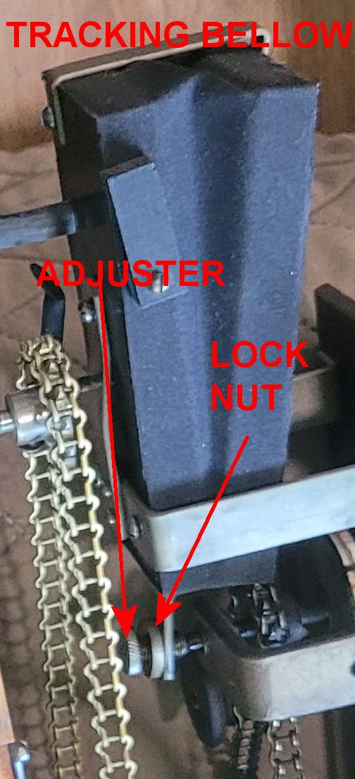
From Doug L Bullock: John, you are correct! The box next to the spoolbox is the primary valve for the sustain unit. The drawings you send would be a correct schematic for this piano player system. You see the breather hole C on the top cover board. It needs no nipple as it only lets atmosphere in to give a large gush of air to the large sustain pouch below, which has no bleed. All the early Aeolians had this primary valve for the sustain which always have a regulator for the sustain pneumatic only. Some of these primaries had Themodist valve attached to the right of it just like Duo-Art does. |

|
Since "Player-Care" is an internet business, I prefer that we correspond via E-Mail (click here to fill out the 'Request Form'). However, if I'm not in the middle of some other activity, you can reach me at 732-840-8787. But please understand that during the hours from 8AM-5PM EST (Mon-Sat), I'm generally quite busy. So, I probably won't answer the phone. If you get the answering machine, please leave a detailed message stating the reason for your call. Also, repeat your name and phone number clearly and distinctly. By necessity, I prioritize everything in my life. And, if you call and just leave your name and number, and ask me to call you back, it might be a day or two before I return your call. Why? Because I don't know why you want me to call and I might not be prepared to assist you in an effective and efficient manner. If you leave me an E-Mail address (which I prefer), spell it out phonetically. The more you do to help me, the more I can help you in return. Don't rush. You have four minutes to record your message. |
|
407 19th Ave, Brick, NJ, 08724 Phone Number 732-840-8787 (Voicemail Only, No Texts) |
