
|

|

|
|
|
|
|
| Home | Manuals | Supplies | Search | Consult | Contact | Testing | Service |
|
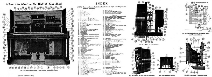
To buy the 1919 or 1916 chart -click here IMPORTANT NOTE: I have not had the time to check every single word, reference, or note in this document. It was scanned and then processed with OCR software which converted it to a text file. That file was processed through Text-to-HTML software to produce this web page. It was then processed by the spell-check software in my HTML program, which found hundreds of errors that I corrected by hand. As time permits, I plan to go over the document line-by-line to make sure it is 100% accurate. It's almost hard to believe that all of this information was squeezed onto one piece of paper measuring just 24" by 29". Also, I am in the process of collecting and 'repairing' the diagrams that are found in the shop chart. As I find better images, the older ones will be replaced. Just below is an interactive image map. Clicking on the various images (and the Index) will take you to the full sized image. Right-clicking on that image will allow you to either print it or save it to your computer. |
|
|
The Gulbransen Player is operated by vacuum power, which is developed by foot power. Vacuum power is air pressure -the weight of the outside air setting certain mechanism in motion while trying to force its way into a partial vacuum. Refer to large illustration above. When the operator pushes down the Pedals (I), the Pedal Levers push open the Exhaust Bellows (2), which normally are held shut by outside springs. This forcible expansion of an Exhaust Bellows produces a partial vacuum inside it. The outside air attempts to enter, through a port in the rear or movable leaf, but is kept out by a leather Flap Valve covering the port. However, air is permitted to enter from the Bellows Equalizers (5) through ports and channels in the Bellows Throat (6). As soon as the foot-pressure on the Pedal is released, the spring at the back of the Exhaust Bellows pushes it shut again. The air just drawn from the Bellows Equalizers is kept from flowing back by a second Flap Valve inside the Exhaust Bellows, covering the port through which it entered from the Bellows Throat; but is allowed to lift the first Flap Valve and escape through the port in the movable leaf. A quantity of air is thus taken from the Equalizers and discharged into the outside air at each complete stroke of each Exhaust Bellows. A spring inside each Equalizer holds it open normally, and resists the pressure of the outside air, thus helping to create vacuum when the Exhaust Bellows suck the air out. This partial vacuum in the Bellows Equalizers then draws air from the Channelboard (22), through the Channelboard Exhaust Tube (54) if the left Gate Valve (59) is open, as it is normally when playing; also from the Motor Pneumatics (31) through the Motor Exhaust Tube (15) if the Tempo Valve (12) is open. The Tempo Valve is controlled by the Tempo Lever (17). It corresponds to the throttle of an engine. The Left Gate Valve is closed by the Reroll Pneumatic (60) when the music sheet is being rerolled. The instrument is played as follows: A music roll is placed between the Chucks (42 and 36), and the tab end is drawn over the Trackerbar (38) and hooked to the Take-up Spool (37). When the music roll is being placed in position, the Reroll Lever (16) should be thrown to the right as far a it will go, for the purpose of unmeshing the Gears (32) of the Transmission (34) and releasing the Take-up Spool so that the music sheet may be hooked to it easily. Now throw the Reroll Lever to the left as far as it will go, to mesh the Gears (32). This act also applies the Brake (83, see detail drawing Figure II) to the Feed Spool Chuck (36) through the Brake Pinion (84), takes the Brake (77) off the Take-up Spool and closes the Control Valve (69, 67, and 66) of the Reroll Pneumatic (60). Now move the Tempo Lever (17) to the right. This act opens, by means of the Tempo Valve (12), a passageway, through the Motor Exhaust Tube ( 1 5) between the Bellows Equalizers (5) and the Motor Pneumatics (31). If the Pedals now be operated to produce vacuum in the Equalizers (5), air will be sucked from the Motor Pneumatics (31), and they will collapse and expand alternately, and turn the Crankshaft (29) and the Take-up Spool (37), thus drawing the music sheet over the Trackerbar (38). The air sucked from the Motor Pneumatics (31) passes through channels in the motor Frame, (30) channels in the Rotating Valves (28), through the Motor Exhaust Tube (15). the Motor Governor (7), the right Bellows Equalizer (5), through the Bellows Throat (6) into the Exhaust Bellows (2), which force it into the outside air. The Motor of the Gulbransen Player is a six-point Motor, there being six Motor Pneumatics, whose power is applied (in push-and-pull movements) at six points on the Crankshaft. Outside air is admitted to the Motor Pneumatics (31) through the Rotating Valves (28) and corresponding channels in the Motor Frame (30). The three forward Pneumatics are served by the left Rotating Valve. The three rear Pneumatics are served by the right Rotating Valve. When one of the Rotating Valves uncovers a port and admits outside air to one of the Motor Pneumatics, it simultaneously shuts off the bellows-suction from that Pneumatic. The Rotating Valves are also "timed," when correctly regulated, so that air is admitted to one Pneumatic of each pair, just at the instant when suction "goes on" in the opposite Pneumatic; which helps to establish smooth torque. The sole function of the Motor is to roll and reroll the music sheet. The turning motion, which the Motor gives to the Crankshaft is communicated to the Take-up Spool (37) or to the Feed-roll Chucks (36 and 42) through the Transmission (34). The Crankshaft turns in only one direction. Rerolling is accomplished by shifting the Gears (32) in the Transmission. Back of each of the 88 ducts in the Trackerbar (38) there is a small tube (called a Tracker Tube) reading to the Channelboard (22), thence through a channel (105, see detail drawing Figure III), to the Diaphragm Chamber (108) of a Striking Pneumatic (96). There are 88 Striking Pneumatics, one for each note or Piano Key. When the Pedals are operated and the music sheet, running forward, covers the Trackerbar, a partial vacuum is created in the Tracker Tubes and Diaphragm Chambers by means of small holes called bleedholes (106) running from the Main Channel ( !04) of the Channelboard into each Tracker Channel (105). Bear in mind that the Left Gate Valve (59) is open when the music sheet is running forward, and therefore the Bellows are sucking air from the Channelboard through the Exhaust Tube (54). Because of the partial vacuum in the Tracker Tubes and Diaphragm Chambers, air rushes into any Tracker Tube as soon as a perforation in the music sheet passes over and uncovers the corresponding Trackerbar Duct, and lifts the Diaphragm (57). The Diaphragm, rising, lifts the Fluted Valve Post (98) and Valve (102), whose head closes a port (101) to the outside air and connects the Main Channel (104) with the interior of the Pneumatic (96), permitting the partial vacuum of the Main Channel to draw the air of the Pneumatic through communicating Channel (99). The air in the Pneumatic is immediately sucked out, the Pneumatic collapses, and the Finger extension (90) of its lower hinged leaf strikes an upward blow upon a Button (95) or block attached to the "Camel-Hump" Sticker (93) of the Piano Action. As soon as the music sheet covers the duct in the Trackerbar again, the Bleedhole, which is never closed, sucks the air out of the Tracker Tube and again creates a partial vacuum in the tube and the Diaphragm Chamber. The blow of the Striking Pneumatic has the same mechanical effect as the blow of the Piano Key (91) in The air sucked from any Striking Pneumatic (96) passes through the Communicating Channel (99) into the Main Channel (104), thence through the Channelboard Exhaust Tube (54), the Left Gate Valve (59), the Bellows Throat (6), the Equalizers (5), into the Exhaust Bellows (2), which expel it into the outside air. The air which enters the Trackerbar Ducts and Tubes is sucked through the Bleedholes (106) into the Main Channel (104), thence through the course described in the preceding paragraph.
The Tempo Valve (12), besides starting and stopping the Motor, also is used by the operator to govern the speed of the Motor, and consequently the speed of the Take-up Spool and the music sheet. It is therefore an important factor in musical expression. When the operator moves the Tempo Lever (17) (o the right, a graduated passageway for the bellows-suction to act upon the Motor is opened through the Tempo Valve. A movement of the Lever to the right increases, and a movement to the left decreases, the size of the passageway.
The music roll is rewound in the following manner: Operate the pedals to produce vacuum. Now throw the Reroll Lever (16) to the right. This act un-meshes the Forward Drive Gears (32), brings into engagement the Reroll Gear Pins (32-c), applies the Take-up Spool Brake (77), and opens the Control Valve (69, 67 and 66) of the Reroll Pneumatic (60), The Reroll Pneumatic immediately collapses and throws the Reroll Thrust (63) and connections to the right, thus closing the Left Gate Valve (59), thereby shutting off the bellows-auction from the Channelboard and Pneumatic Stack; and opening the Right Gate Valve (13), thus allowing the -whole power of the bellows to act directly upon the Motor -without passing through the Motor Governor and the Tempo Valve, as it must -when the music sheet is running forward -which causes the Motor to run at high speed, and as the Gears in the Transmission have been shifted, the music sheet- is rerolled rapidly and silently upon its own spindle.
Press the Silencer Button (33) in the Spoolbox (39). This action lifts the Head (69) of the Control Valve (66) of the Reroll Pneumatic (60), thus admitting air to the Control Tube (49) and the Diaphragm Chamber of the Pneumatic, which collapses and closes the Left Gate Valve (59) and opens the Right Gate Valve (13). with the same results as when the Reroll is operating, except that the music sheet runs forward rapidly and silently. Note that the same pneumatic mechanism is used in Silencing as in Rerolling. The difference is that in Retelling the Transmission Gears (32) are shifted to reverse position, while in Silencing they remain in forward or playing position. (NOTE -The Reroll Pneumatic (60), Diaphragm Chamber and Control Tube are "bled" directly into the left Bellows Equalizer (5), through a channel in the valve block (62) to which the Pneumatic is attached.
The Automatic Sustaining Pedal is operated as follows: Push the Control Switch (44) backward. This action opens a passage way between the Connecting Tube (114, see detail drawing, Figure V) and the Control Tube (48). The former runs from the Sustaining Pedal Air Duct (41) in the Trackerbar (38) to the Switch (44). The latter runs from the Switch to the Diaphragm Chamber of the large Sustaining Pedal Pneumatic (57). When a marginal perforation in the music sheet passes over and uncovers the large Duct (41), the air, rushing through the Connecting Tube (114), through the open Switch (44) and the Control Tube (48), enters the Diaphragm Chamber of the Pneumatic (57) and operates a valve (similar to the valve of a Striking Pneumatic), which opens the way, through Exhaust Tube (55), for the bellows-auction to exhaust the air from the Pneumatic (57) and collapse it. Striking upward, the Pneumatic lifts the Damper Rod (58) of the Piano, just as the Sustaining Pedal of the Piano does when pressed down by the foot, thus pulling the dampers away from the strings.
Four of the1 Expression Levers are non-pneumatic. They are, the Sustaining (51), Soft Bass (52), Soft Treble (53), and Keylock (18) levers. The Sustaining Lever acts directly upon the Dampers of the Piano Action, lifting the dampers away from the strings;. The Soft Bass Lever lifts the left half of the Divided Hammer Rail; and the Soft Treble Lever lifts the right half. The Keylock Lever lifts a rail,; running lengthwise of the keybed, which locks the keys and keeps them from moving when the Stickers of the Piano Action are raised by the Striking Pneumatics. To Tune the Piano. -If there is not sufficient room for the Tuning Hammer between the Spoolbox and Motor and the Tuning Pins, unscrew both Thumbscrews (26), raise the Hinged Spoolbox Brace (43), and tilt the Spoolbox Shelf (27) forward. To Regulate the Piano Action. -Tilt the Spoolbox Shelf forward, as described in the preceding paragraph, thus gaining access to the Regulating Screws (111) of the Piano Action. It is unnecessary to remove the Player Action. To Adjust the Piano Action to the Player Action. -Tilt the Spoolbox Shelf forward, as described above, to gain access to the Player Regulating Screws (94). Connection between the Player Action and the Piano Action usually is made as shown in the sectional drawings, (Figures III and IV) of the Pneumatic Stack. The lower, hinged, leaf of each Pneumatic (96) should rest upon its Rest Rail (88), and the Regulating Button (95) should just touch the Finger (90) of the Pneumatic. If there is any "lost motion" -or space- between the Button and the Finger, the Piano Hammer will not "repeat" smoothly, and considerable "lost motion" may cause a thumping sound or a weak volume of tone. On the other hand, if the Button bears too heavily upon the Finger, the Piano Hammer will be lifted off its Rail. Detect "lost motion" by using a test-roll. If it is slight, or is found in some notes and not in others, adjust by turning down the Player Regulating Screws (94). Proper adjustment is indicated when the Regulating Screw and Button begin to lift the Piano Hammer off its Rail. Stop at this point and ease the Screw back slightly, so that the shank of the Hammer rests upon the Hammer Rail. A special screwdriver, fitting over the heads of the screws, is to be used. (NOTE. -Be sure the Piano Action is in regulation before trying to regulate the Player Action.) If there seems to be considerable "lost motion," ascertain how much, by removing the Shelf and Fallboard of the Piano, inserting the hand under the lower bank, or tier, of Striking Pneumatics and pushing gently upward on them, The distance the hinged leaf of one of these Pneumatics will rise before starting to lift the Piano Hammer off the Hammer Rail is the amount of "lost motion." Make this test along the whole length of the Stack to ascertain whether or not there is more "lost motion" in one section than in another. If there is more than one-eighth of an inch of "lost motion" throughout, raise the Stack, as follows: Loosen the upper screws in Slotted Braces (21), with pliers turn up the Jack Screws (20) and the Supporting Screws (19), which run between the; Keybed and th? Channelboard (22) at the two breaks in the Keyboard, the necessary amount. Then tighten the Brace Screws again. Smooth up the regulation of the individual Pneumatics by turning the Regulating Screws (94) up or down, as necessary. In cases of too close contact between the Player and Piano Actions, (indicated by the Piano Hammers being lifted off the Hammer Rail, and a tendency in the Hammers to "block" against the Strings), adjust by turning up the Regulating Screws (94) or, in serious cases, lowering the Player Action. The Player Action may also be moved out or in, by loosening the lower screws in the Slotted Braces (21). (NOTE. -In earlier models of the Gulbransen Player Piano, the contact between the Player and Piano Actions was sometimes made on the wippens instead of the patented "Camel-Hump" Stickers. The method of adjustment was much the same as described above; that is, through Regulating Screws and Buttons which touch the Pneumatic Fingers when in regulation. Also, in some of the earlier models, the Pneumatic Stacks were mounted on blocks screwed to the Cheeks of the Piano case. To raise or lower the Stack in these models, it is necessary to remove the supporting screws, plug the old holes and bore new holes higher or lower, as required.) The purpose of the Pneumatic Rest Rails (88) is to fix the "throw" of the Pneumatics; that is, the distance the hinged leaf lifts in making a stroke. In theory, the "throw" of the Pneumatic should be the same as the "throw" of the Piano Key, measured at the point directly under the Regulating Button (95); but in practice, it is advisable to allow the Pneumatic a "full," or slightly longer, "throw." The Rest Rails are adjustable; the two upper rails may be moved up or down by loosening the Adjustment Screws (89, see Figure III); the lower rail may be raised or lowered by turning the Adjustment Screws (89) in or out. To Remove a String from the Piano. -This may be done in some instances without disturbing the Player Action. In other cases, it may he necessary to remove the Bellows Set, or Lower Action, first, to reach the Hitch-pins. To Remove a Piano Key -the key be lifted nut after removing the Shelf and the Fallboard of the Piano case. To Remove the Upper Action. -The entire Upper Action, consisting of the Spoolbox, the Motor, the Transmission, the Pneumatic Stack and its enclosing cabinet work, is removable as a unit. Disconnect all Tubes (15, 48 and 49); disconnect the inner wire extensions of the Tempo (25) and Reroll (24) Levers; loosen the set-screw holding the Hinged Spool Brace (43) to the Piano Plate; take out the screws in the feet of the Slotted Braces (21), supporting the Pneumatic Stack; take out the screws in the forward ends of the two Wire Braces (23), running from the top of the Channelboard to the Piano Action Bracket at either end of the Stack; lift Action out of case. To Remove the Lower Action, -The entire Lower Action, consisting of the Bellows Set and the Pedals, is removable as a unit. Disconnect Tubes (15, 54, 55, and 49) at the Bellows; disconnect the wire extension of the Tempo Lever by removing the Leather Nut (11); NOT at the Coupling (14). Fold up the Pedals (1); loosen the Thumbscrew (64) at the top of the Bellows Set; take out the screws in the feet of the two metal Braces (3) ; lift Action out of case. To Clean Out the Bleedholes. -This may often be done by applying a suction pump to the Trackerbar Ducts. If. after using the suction pump, the test-roll discloses Pneumatics that will not "repeat," or that "repeat" sluggishly, mark the Ducts, then open Drop-door (47) by taking out Screws (46), disconnect the Tracker Tubes of the sluggish notes at the Channelboard Nipples (103), take a two-foot length of Tracker Tubing, cover one end of it with a handkerchief to keep dust out of your mouth, apply the other end to one of the marked Trackerbar Duct, and blow and suck, to loosen and remove any dust or paper lint that may be sticking in the Tracker Tube. Then remove the Bleedhole Cups (50), take the same two-foot piece of Tubing, insert one end of it in the Bleedhole Chamber (107) of the sluggish Pneumatic, and again blow and suck, to dislodge any foreign matter. If the Bleedhole is visibly obstructed, and the blowing and sucking does not remove the obstruction, dislodge it with a fine wire or a cambric needle -taking care not to enlarge the hole without reason. (NOTE. -A suction pump may be improvised by disconnecting one of the large Exhaust Tubes from the Bellows Set, applying one end to the Trackerbar Ducts, covering the other end with a handkerchief, and sucking on it.) To Alter the Bleedholes. -When a Pneumatic remains sluggish after a thorough cleaning out of Tracker-bar, Tracker Tube, Bleedhole, etc., it is reasonable to conclude that the Bleedhole requires a slight enlargement; but this must be done carefully, as the Gulbransen is a high-tension Player, and if the Bleedhole is made too large, so much of the air entering at the Trackerbar will be sucked through the Bleedhole that not enough will remain to lift the Diaphragm (97) and seat the Pneumatic Valve ( 102). Use, when necessary, a tapered tool, such as a small awl, to enlarge the Bleed slightly, then test to see whether the repetition is improved. In case of enlarging the Bleed too much, round one end of a one-eighth inch wire, and press gently upon the burr edges of the Bleedhole; this will partly close the hole. To Regulate the Motor. -The amount of vacuum power, or bellows-suction, allowed to reach the Motor from the Exhaust Bellows and Equalizers determines the speed at which the Motor will run or the music sheet will travel; and is governed, first, by the Tempo Lever (17) through the Tempo Valve (12), and, second, by the Motor Governor (7). The Tempo Valve fixes the speed at which the Motor is to run. The Governor makes it run steady. The Governor is a small bellows through which the auction must pass to reach the Motor when the Right Gate Valve (13) is closed. By means of the Governor Spring (8) and its Regulating Screw (!0), the Governor is adjusted to remain nearly open until the air-pressure upon it exceeds a certain weight. When the pressure becomes more than the given weight (because of heavy, rapid pedaling) the resistance of the Spring is overcome, and the Governor starts to collapse. In closing, or nearly closing, the hinged leaf of the. Governor partly closes a valve inside, and reduces the size of a channel leading from the Right Bellows Equalizer into the Governor. This shuts off a part of the high tension, or suction, that the heavy pedaling has developed in the Equalizers, and keeps the Motor from "racing" as it would if the channel to the Motor were fully open. On the other hand, if the bellows-tension should become very light (because of light or slow pedaling), the Spring (8), being then stronger than the air-pressure, would pull the Governor fully open, thereby opening the inner valve wider, allowing more of the power to reach the Motor, and thus prevent it from "dragging" or running too slowly. By fluctuating, up or down, accordingly as the operator pedals lightly or heavily, the Governor allows the right amount of power to reach the Motor to keep it running steady. Theoretically, the Motor should run the music sheet over the Trackerbar at any speed shown on the Tempo Scale (40), at which the Tempo Indicator is stationary, regardless of whether the operator pedals lightly or heavily. (For example, with the Tempo Indicator stationed at 70, seven feet of music sheet should pass over the Trackerbar in one minute; at 80, eight feet, etc.) The average amount of auction reaching the Motor when the Tempo Indicator, Lever and Valve are stationary, and therefore the average speed or "timing" of the music sheet is controlled by the Motor Governor Spring (8). To "time" the music sheet, mark off seven feet on a music sheet, having an average number of perforations, set the Tempo Indicator at 70, and run the measured length over the Trackerbar. If approximately seven feet cross the Trackerbar in one minute, the Governor Spring is in regulation. If only six feet or less cross in one minute, regulate by turning the Regulating Screw (10) in. If eight feet or more run through, regulate by turning the same Screw out. In either case, give the Screw only one quarter turn at a time, then test. Do not disturb the Governor Spring, unless you are sure the Motor needs "timing." (NOTE. -Make sure that the Tempo Valve is in regulation before "timing" the sheet.) Ordinary "racing" or "dragging" of the Motor and music sheet (if due lo Governor trouble) may be corrected by means of the Motor Governor Regulating Screw (9). This screw bears upon a lever which determines the maximum and minimum opening of the inner Valve. If the Motor shows a tendency to "race" under heavy pedaling, turn the Screw in; if it "drags" under light pedaling, turn the Screw out. Give it only one quarter-turn, then test. NOTE. -"Racing" and "dragging" do not always indicate that the Motor Governor is out of regulation. See "Suggestions" for other causes. To increase or Reduce the Tension on the Music Sheet. -Tighten or loosen the Brakes (77 and 83) in the Transmission. These Brakes are always adjusted at the factory, and it should be unnecessary to change their tension until the Player has had considerable wear. Their purpose is to keep the Feed Spool and the Take-up Spool running at the same speed. The Feed Spool Brake (83) may be tightened by giving its Regulating Screw (79) a fractional turn to the right, or loosened by turning the Regulating Screw to the left. The Take-up Spool Brake (77) may be tightened by giving its Regulating Screw (80) a fractional turn to the right, or loosened by turning the Regulating Screw to the left. The Brakes should allow the sheet to run freely, but without "looping." To Make a Music Roll Track. -If a music roll is running unevenly, reroll it, remove it from the Chucks, and, holding it in the right hand with the tab end toward you, tap the right end sharply into the palm of your left hand, to settle the roll flush against the right or stationary flange. Then fit the movable left flange snugly against the left end of the roll, put the roll back in the Chucks, run it across the Trackerbar and see that the Ducts are in alignment with the perforations. Use the Transposing Device to align the Ducts. If the roll does not then run straight, it is defective, and should be returned to the roll manufacturer. (NOTE. -A loose Take-up Spool Brake is sometimes the cause of faulty tracking. If the sheet "loops" when rerolling, it is likely to wind up unevenly and, of course, unwind unevenly the next time played.) To Operate the Transposing Device. -See the two long vertical lines (35) near the ends of the Trackerbar (38). When the edges of the music sheet touch these two lines, the music will be played in the signature key, usually marked on the music roll or the roll-box. To transpose to a higher key, turn the Transposing Knob (45) toward you. To transpose to a lower key, turn the Knob from you. To "Time" the Rotating Motor Valves. -The Motor Valves (28) must rotate in such relation to the Ports in the Valve Seats (116, see detail drawing Figure VI) that air will be admitted to one Pneumatic of each pair at the moment when the bellows-suction starts to collapse the opposite Pneumatic. To adjust the Left Rotating Valve (28), loosen the Set Screw (117) of tie Valve Guide (118). Then set the middle Pneumatic Arm (74) at dead center forward; that is, with the "throw," or projection, of the Crankshaft exactly level, the Pneumatic Arm fully advanced and nearly level, as shown in detail drawing Figure VI. Now turn the Valve. (28) until the Guide (1 [8) is approximately vertical and the slot in which the Guide rests is up. With the Valve in this position, the upper Port through the Valve Seat (116) should be covered, but any backward rotation of the Valve should immediately open this top Port. Holding the Valve in this position, and without disturbing the dead-center-forward position of the Pneumatic Arm and Crankshaft, set the Set Screw (117) sufficiently to hold the Valve in place, then turning the Crankshaft slightly to put the Set Screw in better position for the screwdriver, tighten the Screw. To adjust the Right Rotating Valve, loosen its Set Screw, then set the middle Pneumatic Arm (74) at dead center rear. Turn the Right Valve until its Guide is approximately vertical and the slot in which the Guide rests is down, (see 118-a), with the upper Port covered but ready to open on any backward rotation of the Valve; then set the Screw. (NOTE. -The Motor Valves are correctly "timed" when they leave the factory, and seldom require readjustment. If the Motor "jumps," search for other causes before trying to reregulate the Motor Valves. See "Suggestions.") To Adjust the Tempo Valve. -Set the Tempo Indicator at "off." Looser, the Wire Coupling (14). Place the Tempo Valve (12) with the Adjustment Slide (on top the Valve) pointing vertically. Operate one Pedal by hand to produce vacuum in the Bellows. Turn the Tempo Valve slowly to the right. Stop at the point where the Motor and the music sheet stop running. Operate the Pedals vigorously to. make sure that the sheet will not "crawl" under high tension. If it "crawls," turn the Valve a little more to the right, and test again. Do not turn farther to the right than is necessary to stop the "crawling." Carefully tighten the screw in the Wire Coupling (14). (NOTE. -The Tempo Valve is set correctly at the factory, and if the Wire Extension of the Tempo Lever is disconnected at the Leather Nut (11), instead of at the Coupling (14) when the Bellows Set is being removed from the case, readjustment is not likely to be necessary.) To Gain Access to Tracker Tubes, Reroll Valve, etc., without removing the Player Action from the Piano, take out the Drop-door Screws (46) and open the Drop-door (47). To Remove the Transmission as a unit, loosen the set-screw in the Right Music Roll Chuck (36), take out the Lower Transmission Frame Screw (70) and two Upper Transmission Frame Screws (85), and disconnect at the Crankshaft Joint (73). To Remove the Motor from the Spoolbox Shelf (27), take out the Motor Footscrews (72), detach the Motor Exhaust Tube (15) at its upper nipple, and disconnect at the Crankshaft Joint (73). To Open and Cover B Bellows or Pneumatic, first remove the rubber-cloth sidewalls and if possible make the inspection or repair without disturbing the end cloth. To cover, cut a new piece of rubber-cloth long enough to extend around the two sides and the end of the Bellows or Pneumatic and wide enough to cover the -wider end when fully distended. Then remove a portion of the old cloth from the end ("but leave enough on to preserve the "throw"), and glue down the new cloth at the end only. As soon as the glue sets, remove the rest of the old cloth and glue the new cloth fully across the end. Again let the glue set, then glue down the new sidewalls; then trim. If a Note "Ciphers," or Fails to Strike, there probably is an obstruction somewhere in the Tracker Tube, the Bleedhole, or the Diaphragm Chamber of the Pneumatic. (a) Apply a suction pump to the Trackerbar. (b) Disconnect Tracker Tube and blow it out. © Blow out the Bleedhole. (d) If necessary, clear Bleedhole with a fine wire. (e) Examine the Pneumatic Valve (102) to ascertain whether it is seating. (f) Examine Channelboard (22) and Valve Shelf (87) for cracks or open joints. If a Key Strikes and Remains Down, air probably is leaking into the Tracker Tube or the Diaphragm Chamber of the Pneumatic, (a) Examine the Tracker Tube carefully for leaks, especially at its connections. (b) Examine the Channelboard for small cracks or open glue-joints. (NOTE. -Make sure the trouble is not a sticking Key or center in the Piano Action.) If the Motor Stalls, the Rotating Metal Valves probably are considerably out of regulation, (a) See if the Guides (118) are working properly in their slots; if out, put back. (b) Make sure that bellows-suction is being developed and that it is reaching the Motor, © Regulate the Motor Valves. If the Music Sheet Stops when the operator tries to strike a "crash" chord, (a) the Motor Governor (7) may be out of regulation; the inner valve closing tightly under heavy tension, which it should not do. Give the Motor Governor Regulating Screw (9) a fractional turn out. (b) The music sheet may be sticking to the Trackerbar; wipe Trackerbar off with Three-in-One Oil, If the Motor Jerks, (a) examine the Transmission to make sure the Forward Drive Gears (32) are fully meshed, if the jerking occurs when the music sheet is running forward, or fully unmeshed and the Reroll Gear Pins (32-c) are engaging properly if it occurs when rerolling. (b) Examine the Transmission Brakes (77 and 83) to make sure they are not dragging too heavily. © Examine the bearings of the Transmission and the Crankshaft to see that they are not binding. (d) See whether there has been any warpage in the Spoolbox Shelf (27) or the Motor Frame (30); warpage here will sometimes cause the Pneumatic Arms (74) to bind, (e) Look at the felt bushings of the Arms (74) to see if someone has made the mistake of oiling them; oil will harden the bushings and develop excessive friction; also see that the Adjustment Screws (75) have not been over tightened. (f) Test the Motor Governor (7); a Motor that needs regulating may seem to jerk, because it responds slightly to each stroke of the pedals, (g) The Rotating Motor Valves may be slightly "out of time"; regulate them. If the Motor "Races," it is getting too much bellows-auction. Turn the Motor Governor Regulating Screw (9) in, one quarter-turn, then test. If a "Racing" Motor Does Not Slow Down, when the Motor Governor Regulating Screw is turned in (a) suction from the Bellows Throat (6) may be acting directly upon the Motor through a leak in the Right Gate Valve (13). Detach the Motor Exhaust Tube (15) at its lower end, and with a screwdriver or lead pencil inserted at the nipple, feel the head of the Gate Valve, to find out whether it is firmly seated, as it should be when the music sheet is running forward. If not seated properly, loosen its outside Set Screw (13), press the Valve head against the seat, and re-set the Screw. But don't disturb the Set Screw unless you are sure the Valve is not seating, (b) The Tempo Valve may be out of regulation. (c) Someone may have over-tightened the Regulating Screw (10) of the Motor Governor Spring; if so, release the excessive tension and "time" the music sheet, (d) The inside Valve of the Governor (7) may be sticking -a rare occurrence, however. Remove the rubber-cloth, open the Governor and ease the sticking parts. Cover the Governor bellows with new rubber-cloth. If the Motor "Drags," (a) it may be getting insufficient power or bellows-suction. Examine the Tempo Valve and connections to make sure they are in regulation, and if the trouble is not found there, turn the Motor Governor Regulating Screw out one quarter-turn, then test the speed of the Motor, (b) Examine the Transmission Brakes (77 and 83) for excessive tension. (c) Examine the bearings of the Transmission (34) and the Crankshaft (29) for excessive friction. (d) The music sheet may be sticking to the Trackerbar; wipe off Trackerbar (38) with a cloth moistened with Three-in-One Oil. (e) The Music Sheet may need "timing"; see paragraph "To Regulate the Motor." (NOTE, -Nothing will make a Motor "race" but an excess of power; and nothing will make it "drag" but insufficient power or some interference with the power, such as abnormal friction.) If the Music Sheet Flutters or Loops, when traveling forward, the Feed Spool (36 and 42) probably is running faster than the Take-up Spool (37). Increase the tension on the sheet-by tightening the Feed Spool Brake (83 and 79). If the sheet loops when rerolling, tighten the Take-up Spool Brake (77 and 80). If the Music Sheet Buckles in the center, the sheet itself usually is defective. Follow instructions under heading, "To Make a Music Roll Track." If this is not successful, reject the roll. If the Pedals Fall from under Foot, there probably is a leak in the Bellows Set. (a) Detach the Channel-board Exhaust Tube (54) and the Motor Exhaust Tube (15); have an assistant cover the nipples of these Tubes with his hands; work the Pedals (I ) to produce vacuum; if there is no leak in the Bellows Set, the Equalizers (5) will be fully collapsed on the fourth or fifth pedal-stroke and pedaling will become hard; if the Pedals continue to fall from under foot, or to work easy, look for the leak. (b) Examine the Leather Flap Valves at the back of the Exhaust Bellows (2) to see if they are stiff or if there is any obstruction that prevents their closing tightly. Under adverse atmospheric conditions, these Leather Valves may lose some of their pliability, and thus permit air-leakage. In such case, they should be taken off and made flexible by rubbing with the hand. Don't use oil; it will soften them temporarily, but make them hard later. © Examine the rubber-cloth and the tube connections of the Bellows for leaks. If the Music Plays on Reroll or Silencer, the Reroll Pneumatic (60) probably is not closing tightly. Pedal harder and watch the Pneumatic; if it closes then, the Return Spring (4) or a small wire spring at the lower end of the Pneumatic itself may be too strong. Lift the Return Spring from its slot and weaken it slightly by bending backwards. If the Sustaining Pedal Remains "on" Continuously, air is leaking into the Control Tube (48) or the Diaphragm Chamber of the Sustaining Pedal Pneumatic (57). Examine the Control Tube and the Switch (44) for leaks, and the valve-block of the Pneumatic for cracks. If the Hammers Do Not Strike a Firm Blow, aud the Tone is Weak, or the Action Makes a "Pounding" Sound, when operating with the Player Action, but respond normally to hand playing, there probably is some "lost motion" between the Player Action and the Piano Action. Adjust as directed in the paragraph "To Adjust the Piano Action to the Player Action." If Some of the Hammers are Raised off the Hammer Rail, the regulation between the Piano Action and the Player Action is too "close." See paragraph, "To Adjust the Piano Action to the Player Action." If the Action Seems Sluggish, the Tracker Tubes and Bleedholes probably need cleaning. See paragraph "To Clean Out Bleedholes." If the Music Sheet "Crawls" when the Tempo Lever is thrown to the left as far as it will go, the Tempo Valve (12) needs readjusting. See paragraph "To Adjust the Tempo Valve." If the Music Sheet Jumps Forward Suddenly when playing air probably is leaking into the Silencer or Re-roll system. Examine the Reroll Control Valve (66), the Control Tube (49) and the valve-block of the Reroll Pneumatic for leaks; the wire Spring (65) of the Control Valve (66) sometimes is knocked out of position, thus permitting leakage through the Port (67). If the Pedals "Kick Back," or rise with abnormal force after being depressed, there probably is some obstruction under the inside Flap Valve of the Exhaust Pedals, which permits the air to flow back into the Bellows Throat. (a) Operate the Pedals vigorously, to suck the obstruction out. (b) If necessary, remove the bellows-cloth to get at the inner Flap Valve. If the Sustaining Pedal Pneumatic Makes a "Sucking" Sound, observe closely to ascertain whether the noise occurs when the Pneumatic collapses or when it opens, or in both cases. If the sound is heard as the Pneumatic closes, and especially if the Pneumatic works sluggishly, (a) the Bleedhole may be partly stopped up. Detach the Control Tube (48) at the Switch (44), cover the end with a handkerchief and blow and suck on the tube to dislodge dust or lint. Access to the Bleedhole may be had by removing the large fibre nipple to which the Exhaust Tube (55) is attached at the Pneumatic (57). On replacing this nipple, seal the joint with shellac. (b) The Bleedhole may be too large, therefore putting too much suction on the Control Tube. Partly close it, as described in paragraph, 'To Alter the Bleedholes." (c)There may be an obstruction -dust, lint, a burr, etc.,- in the Switch (44). Attach a short flexible tube to the lower nipple of the Switch, turn the Switch "on," blow on the tube, and hold the hand near the large Duct (41) in the Trackerbar to feel the air current and determine whether or not the channel is free. The Switch may be removed from the Spoolbox by taking out the machine screw running through it. Upon replacing the Switch, seal it in with shellac to prevent its turning. (d) There may be burrs or rough edges on the nipple of the large Duct (41). Paint them with shellac. (e) There may be a slight leak in the Pneumatic, (f) The Pneumatic may have too much "throw," I. e., opening too much. Adjust by lowering the metal stop (56, on rear top of Pneumatic), which controls the stroke of the rear lever-arm. If the sound occurs when the Pneumatic opens, the inflow of air is not being properly muted. Place an additional piece of felt over the top. If "Sucking" or "Hissing" Sounds are Heard at the Trackerbar, they probably are caused by air flowing over small metal burrs in the nipples back of some of the Tracker Ducts. Use a test-roll to locate the noisy Ducts. With a toothpick, or similar small hardwood slick, dipped in shellac, paint the burrs or rough edges of the nipples. A Squeak in the Player Action usually will be located in one of the bearings of the Transmission or the Pedals. These metal bearings should be oiled occasionally with a little light oil, such as Three-in-One Oil. These are the only parts of the Player that require oiling. Do not oil the Rotating Motor Valves or the Crankshaft Bearings; use dry graphite here if lubrication becomes necessary. (NOTE. -Make sure that a squeak supposed to be in the Player Action is not really in the Piano Action.) A squeak in the Pedals, if not cured by oil applied to the bearings, probably is caused by loose treads. Fold up the Pedals and tighten the screws in the bottom of the treads. A Continuous "Whistle" or Creaking usually is caused by a dry pad on one of the Transmission Brakes. If it is heard when playing, lubricate the Feed Spool Brake (83); if when rerolling, lubricate the Take-up Spool Brake (77). Use graphite, putting it on the pad with n knife-blade, In case of Pneumatic Valve trouble, do not try to open up the Channelboard or Valve Shelves, but box up the Pneumatic Stack and send it to the factory. If not sure it is valve trouble, write a complete description of it to the factory before forwarding the Stack. In Making Complaints to the Factory, please state the symptoms of the trouble as fully as possible in your first letter; that is, tell in detail how the mechanism acts, or what parts fail to act. Use the index numbers and names shown on this Shop Chart.
|
| Player Piano Reference Materials - Click Here |

![]() ..To
The Top of this Page . . . . . . . . . . .
..To
The Top of this Page . . . . . . . . . . . ![]() ..To The HOME Page
..To The HOME Page
|
Since "Player-Care" is an internet business, I prefer that we correspond via E-Mail (click here to fill out the 'Request Form'). However, if I'm not in the middle of some other activity, you can reach me at 732-840-8787. But please understand that during the hours from 8AM-5PM EST (Mon-Sat), I'm generally quite busy. So, I probably won't answer the phone. If you get the answering machine, please leave a detailed message stating the reason for your call. Also, repeat your name and phone number clearly and distinctly. By necessity, I prioritize everything in my life. And, if you call and just leave your name and number, and ask me to call you back, it might be a day or two before I return your call. Why? Because I don't know why you want me to call and I might not be prepared to assist you in an effective and efficient manner. If you leave me an E-Mail address (which I prefer), spell it out phonetically. The more you do to help me, the more I can help you in return. Don't rush. You have four minutes to record your message. |
|
407 19th Ave, Brick, NJ, 08724 Phone Number 732-840-8787 (Voicemail Only, No Texts) |
