
|

|

|
|
|
|
|
| Home | Manuals | Supplies | Search | Consult | Contact | Testing | Service |
|
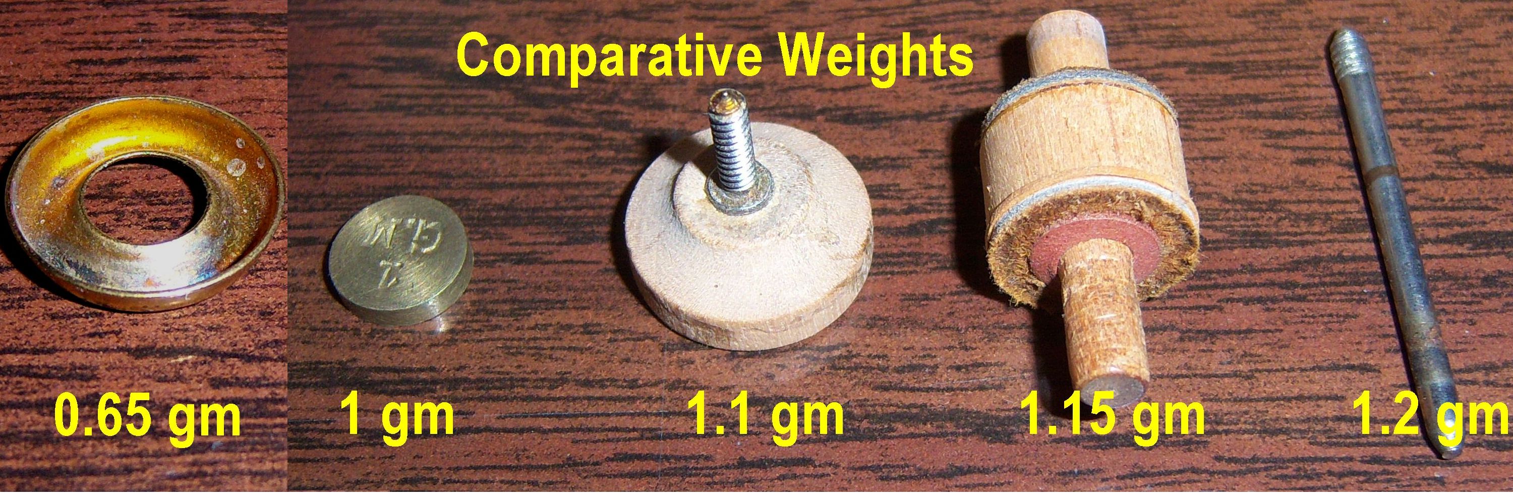
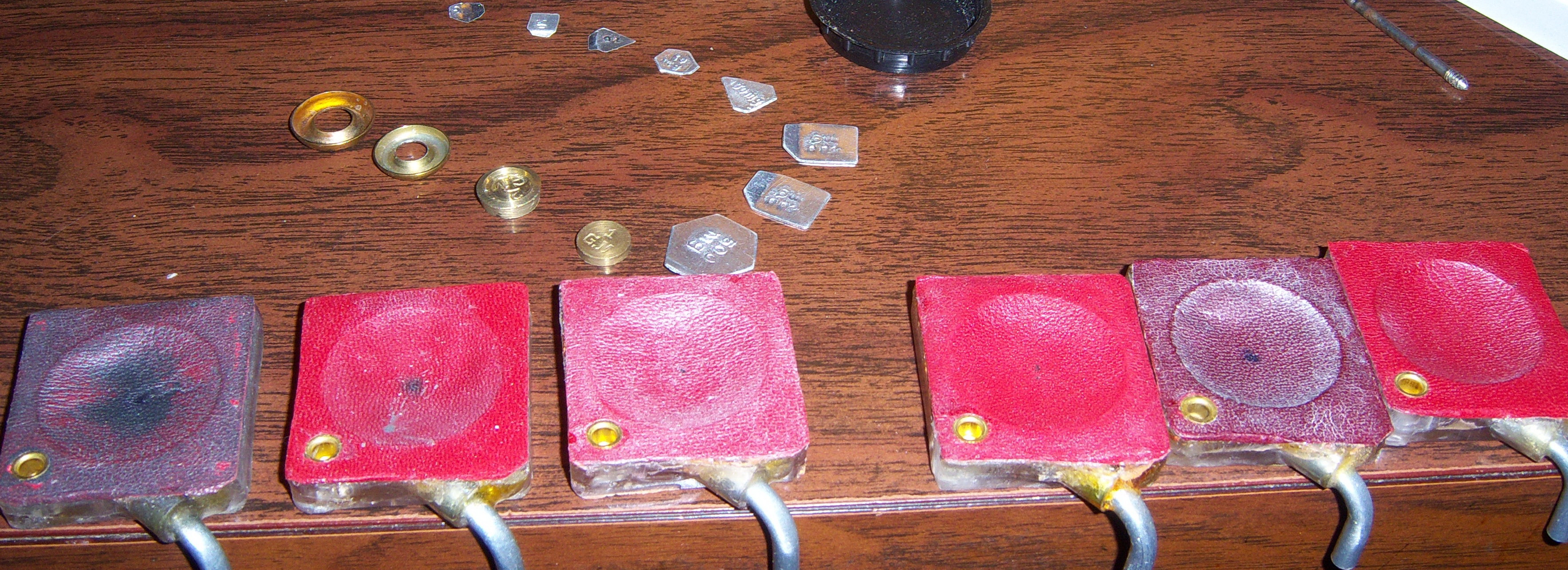
As was pointed out in Craig Brougher's article, "What's the Best Pouch Sealant", there are over a dozen variables that need to be considered when testing a pouch sealant. He also states, "The tighter the sealant, the stiffer the pouch. Sorry about that, but it's just a physical law of nature." Obviously, flexibility and sensitivity are very important characteristics of a pouch. However, having read numerous articles by various individuals, the one thing that most people seem to be concerned about is how long will the sealant do its job. What good is a sealant that leaves the pouch flexible and sensitive if it's sealing capabilities diminish over time? Conversely, if a sealant decreases the sensitivity and/or responsiveness of the pouch, does it really matter how long it lasts? Another variable that should be considered is where the pouch will be used. Sensitivity and responsiveness are generally only critical in units that operate at vacuum levels of around 5" (five inches WC). However, before we can have a meaningful conversation about 'sensitivity' and 'responsiveness', we must clearly define those words. In player pianos, the sensitivity of a pouch is defined as the amount of effort that's required to inflate the pouch to the point where it will change the state of the valve from 'off' to 'on'. As a general rule, the more air-tight the pouch is, the more sensitive it becomes. Another factor that effects the pouch's sensitivity is its stiffness. The stiffer the pouch gets, the less sensitive it becomes. That being the case, an obvious conclusion is that a pouch that's not air-tight but very flexible could be just as sensitive as one that's more air-tight but stiffer. In player pianos, the responsiveness of a pouch is defined as the length of time it takes for the pouch to inflate enough to change the state of the valve from 'off' to 'on' and then deflate back to the point where the valve turns 'off' (one full cycle). There are a number of factors that effect the responsiveness of a pouch. Obviously, its flexibility is one of those factors. And, the more flexible the pouch is, the less time it is going to take for the pouch to complete a full cycle. Another factor is the air-tightness of the pouch. However, unlike sensitivity, the more air-tight the pouch gets, the longer it's going to take for the valve to complete a full cycle. That's because it will take longer for the bleed to suck the atmosphere out of the pouch well if the pouch is air-tight than it will if the pouch leaks to some degree. (If the pouch is leaking somewhat, it helps the bleed suck the atmosphere out of the pouch well.) That being the case, an obvious conclusion is that a pouch that's not air-tight but very flexible could be just as responsive as one that's more air-tight but stiffer. So, as it relates to sensitivity and responsiveness, and taking for granted that the stiffness of two pouches are identical, it should be clear that an air-tight pouch is more sensitive but less responsive than a pouch that is not air-tight. Conversely, a pouch that is not air-tight is more responsive but less sensitive than a pouch that is air-tight. Under real-time operating conditions, there are 14.7 lbs/sq in of pressure, minus the negative pressure from the bleed, used to inflate the pouch. However, in order to more accurately test the flexibility of a pouch, real-time operating conditions cannot be employed because the degree to which the pouch 'leaks' (or bleeds) when different sealants are applied is an unknown factor. Therefore, to determine the flexibility of the pouch, calibrated weights were incorporated. (The dish of all of the pouches was set with a pouch setting tool; which creates a 1/8" dip in the center of the pouch.) During the initial testing of untreated pouches, the weights shown below were selected for two reasons. One, to see how little weight was required to deflate the pouch. Two, to show how little weight was required as compared to the lightest of valve parts. The part on the far right is the valve stem from a Standard action. Next to it are the expression valve from the 'miniature' Duo-Art expression valve assembly and (next) its associated valve stem. Next is a 1 gram calibration weight. Lastly pictured, a #10 countersunk washer. It was later found that the #8 countersunk washer, which weighs 0.53 gm, was a better choice for testing the stiffness of the completed pouches. It might also be of interest to note that one button from a primary valve in a Standard Double-Valve Action weighs 0.45 gm. (Primary valves of this type are comprised of two buttons, a piece of wooden dowel rod, and two valve facings.)
Here are the results of the six tested pouches before they were sealed: The only thing this test really proves is that all of the pouches deflated using a weight that is about 1/2 as heavy as the lightest part of the lightest valve that was tested (weighed) and that they are all almost identical. However, it did indicate that perhaps a better method of testing for flexibility/stiffness was needed. (Results of this same test after the pouches were sealed is below. Click Here) Perhaps one of the more difficult aspects of testing sealants on leather is the fact that no two pieces of leather are exactly the same. Even if the pieces are only an inch apart on the skin, they aren't "exactly" the same. This complicates the making of the sample pouches because each sample is ever-so-slightly different (as shown above), and comprehensive testing requires that all variables be taken into consideration. For this reason, another type of flexibility/stiffness tester was constructed. (see below)
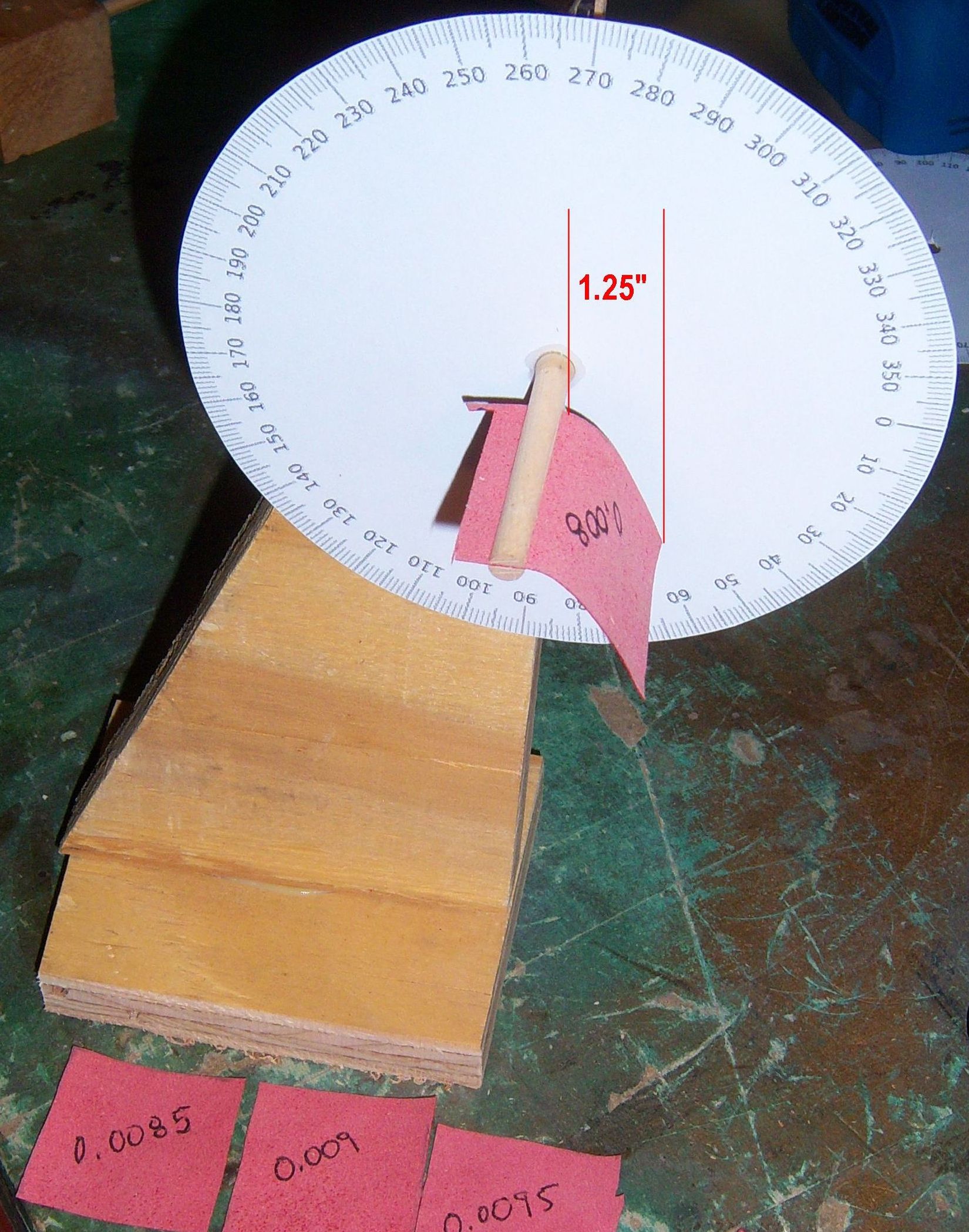
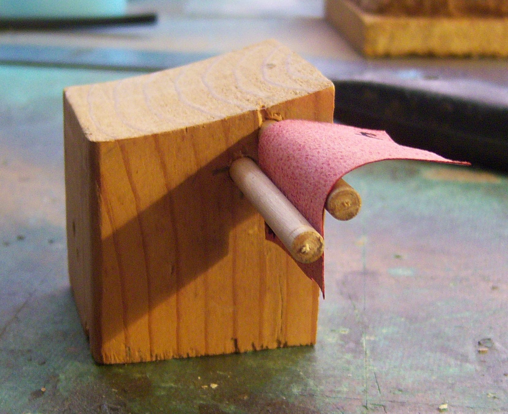 Problem: The above tester lacks the ability to come up with actual numbers. So another piece of equipment was designed and constructed. The results shown below represent the number of degrees that the leather was bending under its own weight. The length of each piece was 1.25". *Note: For the testing of the first six samples, the gauge is initially set so that '0' degrees pointed to the right and '270' degrees pointed up for the 'Curve Right' test. Then it was rotated 180 degrees for the 'Curve Left' test. The results are explained below the chart. |
 |
|
|
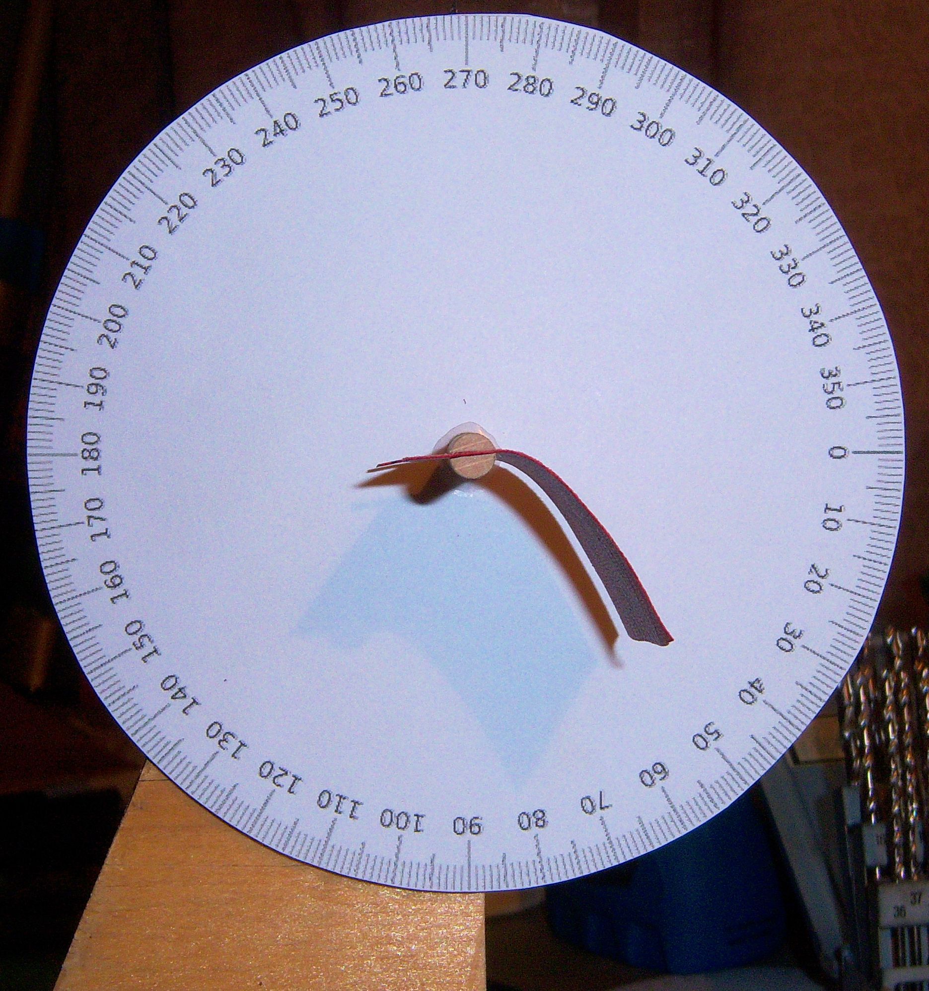
All leather has somewhat of a natural curl because it comes from an animal. As a result, it naturally bends in one direction more easily than it does in the opposite direction. For that reason, two measurements were taken for each piece; One at '0' degrees and one at '180' degrees. With regards to the first six samples, by adding the two numbers and dividing by two, you arrive at the average for each piece. These numbers are only used to show the relative stiffness of the various thicknesses of this particular leather. All of the pieces shown came from different areas of the same skin. The results of the tests on the first six pieces clearly indicate that the thickness of the leather does not necessarily mean that it is stiffer. All six of the 0.0065" pieces hung down to the same angle when put in the tester (60 degrees). Therefore, in order to determine the relative stiffness of the pieces to each other, a slightly different technique was used to establish the numbers shown in the parentheses. The technique that was used is explained as follows: The test piece was installed at the '0' degree setting with the leather hanging down on the right side of the center pole (Curve Right). Then the dial was rotated counterclockwise until the leather 'flipped' over to the left side of the holder. The point at which it 'flipped' over to the left side of the holder is the number in the parentheses. Then the dial was rotated clockwise until the leather 'flipped' over to the right side of the holder. The point at which it 'flipped' over to the right side of the holder is the number in the parentheses. Again, remember that these numbers only represent the relative stiffness of the pieces as compared to each other. The rationale for testing the leather in this manner will be cleared up later in this treatise. |
|
*Note: For the testing of the six 0.0065" sealed samples, the gauge is initially set so that '0' degrees pointed to the right and '270' degrees pointed up for the 'Flip Left' test. Then it was rotated 180 degrees for the 'Flip Right' test. The results are explained below the chart. |
|
 |
|
|
As demonstrated in the video, all of the sealers had a noticeable effect on the stiffness of the leather. Interestingly, the only sealer that made the leather more flexible was the Hydrophane. More information about the effect that the sealer had on the pouches is below. (Click Here) |
|
A bleed cup and the six unsealed pouches were tested at 1" of vacuum. The "bubble rate" (which will make more sense after you've seen the video and the picture below) for each of the tested elements is as follows: Bleed - 49/2 sec., Pouch 1 - 27/2 sec., Pouch 2 - 20/2 sec., Pouch 3 - 20/2 sec., Pouch 4 - 28/2 sec., Pouch 5 - 27/2 sec., Pouch 6 - 23/2 sec. (Conclusion/Opinion -see below)
YouTube video located at: https://youtu.be/VHYOo4bV4xM
the air passing through the bleed cup and each of the six unsealed leather pouches. 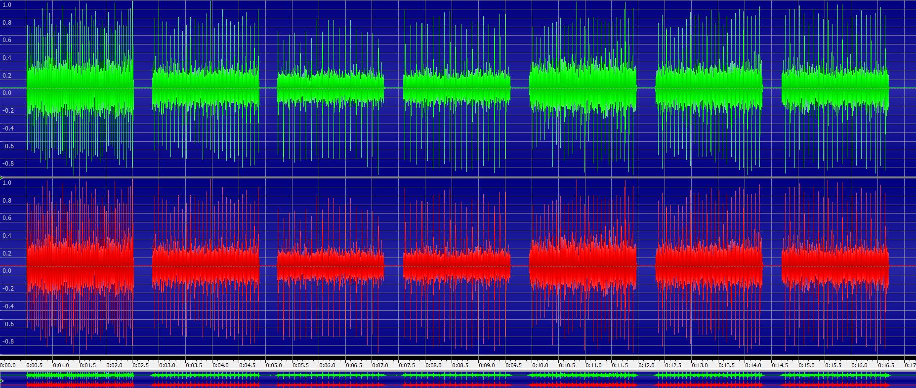 Click on image to see full size picture
Each segment of the audio file is 2 seconds in length
In my opinion, the logical conclusion that can be reached is that the average 'leakage rate' of the six pouches is 1/2 of the 'leakage rate' of the bleed cup. And, since the responsive capability of any pouch is (all other factors being the same) the comparative difference between the amount of atmospheric air coming into the pouch well minus the amount of air being sucked out of that well by the bleed cup, it seems only reasonable to conjecture that additional leakage of air into the well via the pouch itself will diminish the sensitivity of the pouch, but that it might improve the responsiveness of the valve. It should also be noted that an increase in the amount of air leakage via the pouch will decrease the amount of power that the pouch has to push the valve off of its intake seat and onto its exhaust seat, and this will diminish the sensitivity of the valve.
The question of whether or not the application of a pouch sealant will improve or diminish the responsiveness of a pouch has yet to be determined. It also remains to be seen if the addition of a sealant will increase or decrease the power that the pouch has to change the state of the valve. This is because it seems only logical that if the pouch becomes stiffer, as a result of the sealant, some of its power, to move the valve, will be lost. All that said, one has to wonder to what degree the benefits gained by sealing the pouch are counteracted by the added weight and/or the increased stiffness caused by the sealant..... Testing continues!
With regards to stiffness; Using the weights mentioned earlier (and other calibrated weights), here are the results of the six tested pouches after they were sealed:
1 (Rubber Cement/Thinner) - more than 0.90 gm., but less than 1.0 gm.
The above results seem to indicate a few interesting points. As compared with the results of the unsealed pouches only one sealant didn't seem to change the stiffness of the leather. In three case, the amount of weight required to deflate the pouch tripled!
The video below is fairly self-explanatory. All it's really missing is a count of the number of bubbles that were generated by each pouch. So, here they are:
Pouch #1 - 19/2 sec.
IMPORTANT NOTE: The pouches were tested again on Aug 31, 2016 after being in use for 1-1/2 months. The applied vacuum was 2". The results given are the number of bubbles per every two seconds:
Pouch #1: 19/2 sec.
(See note below). Clearly, there are differences in the amount of leakage. I cannot explain these differences. I'm just presenting my findings.
Things are starting to get interesting. Judging strictly by the results of the weight tests and the bubble jar tests, it seems fair to say that the sealant that decreased the sensitivity and was the least effective at sealing the leather was #6. Conversely, the sealant that seems to have slightly increased sensitivity and significantly reduced leakage was #3.
YouTube Video of the Testing Sealed Pouches
AMENDMENT TO BUBBLE TEST FOR BLEED AND UNSEALED POUCH AT 1" and 2": Bleed leak rate at 1": 41, Bleed leak rate at 2": 51; Pouch leak rate at 1": 5, Pouch leak rate at 2": 18 |
|
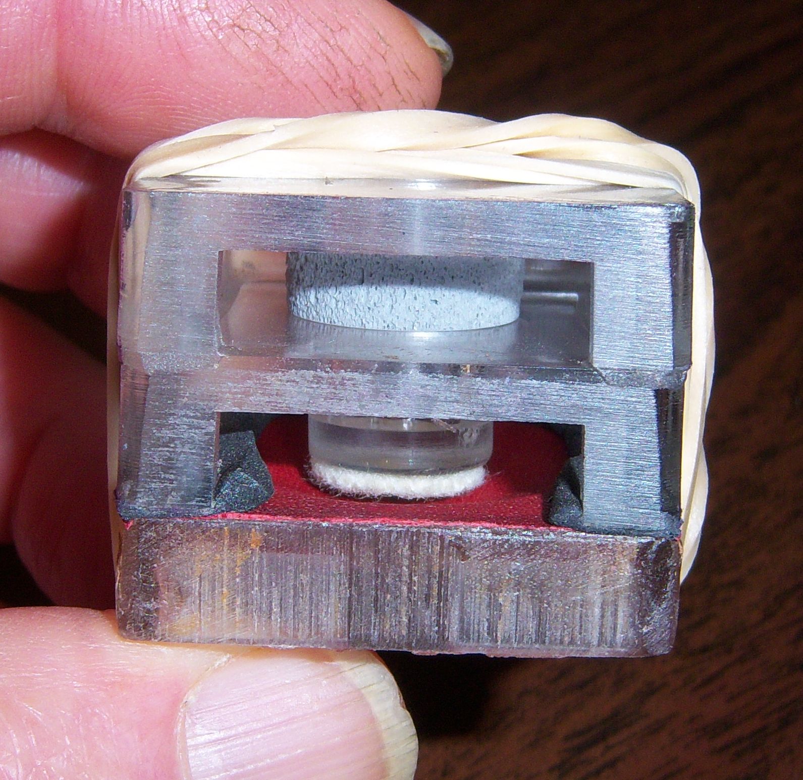
Without question, two of the three most important tests are the 'Sensitivity' and 'Responsiveness' tests. The other is the 'Longevity' test, which may take months to complete. The first two will be done independently. To test for 'Sensitivity', a test valve was made that could be attached to each of the six pouch assemblies. The valve facing and valve stem are very light, weighing only 1.2 gm. and the facing, being made out of a smooth closed cell silicone material, it is 100% air-tight. The valve travel is set to precisely 0.020". The pouch-to-stem clearance is set to 1/16".
 In an effort to test every aspect of the operation of the pouch, valve, and pneumatic, this valve was attached to a variety of different jigs. Initially, the vacuum level was set to 1" WC. Naturally, all of the surfaces of the wooden test block were well sealed both inside and out, as were the boards of the test pneumatic. Everything is as air-tight as possible.
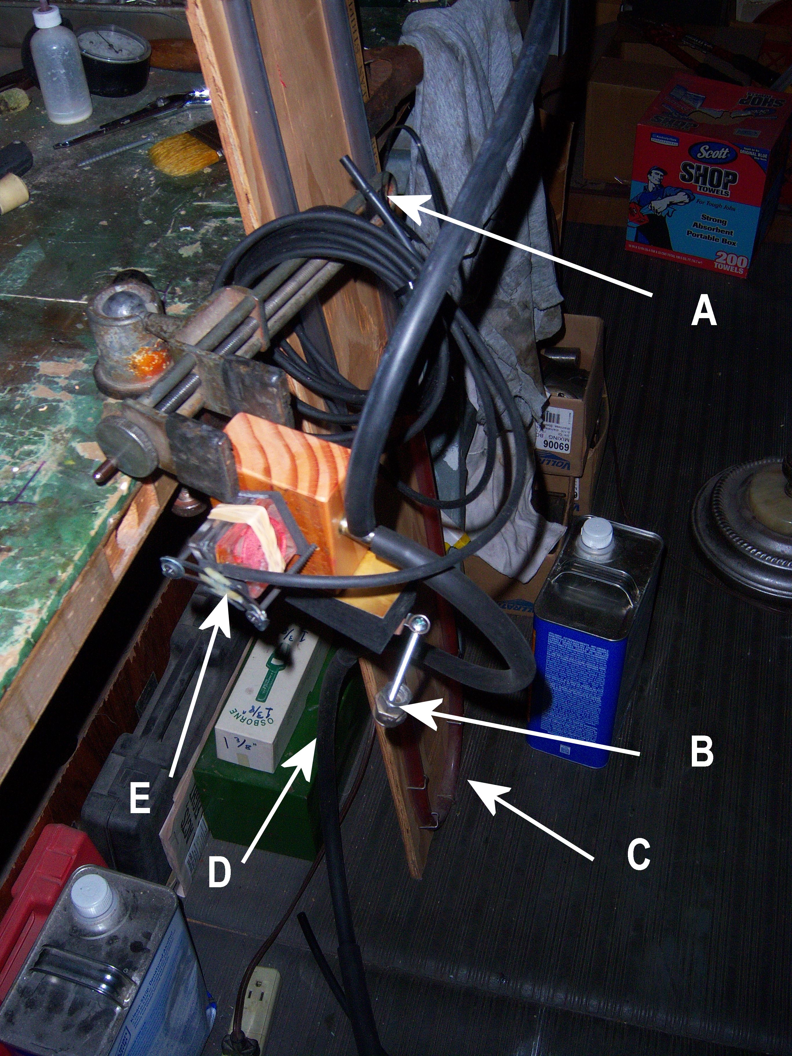
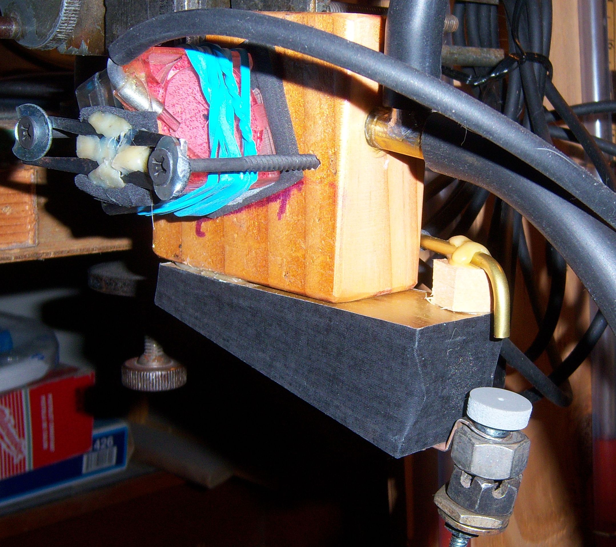
Legend: A; 12 ft of trackerbar tubing, B; 50 gm. of weight, including the bolt, C; Mamometer, D; 3/8" ID vacuum supply hose, E; Ampico B expression spring used to hold the valve tightly against the 1/16" closed cell neoprene gasket, First, the pouches were checked to see if all of them would operate on 1" of vacuum without any trackerbar tubing connected to the elbow. All of them worked without a problem. Then 12 ft. of trackerbar tubing was connected. Of the six pouches, only #1 reacted smartly. #3 and #6 reacted within about a second, and #4 reacted in about two seconds. #2 and #5 did not react at all. So, it was concluded that #1 was the most sensitive, followed by #3 and #6 -which appeared to take an equal amount of time to react. (NOTE 1: At this point, it was later found that #1 had a clogged bleed. So, obviously it was more sensitive than all the other test subjects.) As for repetition, considering that only the #1 pouch repeated as fast as the end on the tubing could be covered and uncovered, it was also concluded that it has the best repetitive capability at 1" of vacuum, with an unloaded pneumatic. (See NOTE 1 above.) Next, 50 gm. of weight (the load) was added to the pneumatic and the vacuum level was increased to the point where the pneumatic collapsed nearly 100%. That required a little less than 4" of vacuum. So, the level was set to 4" for all of the tests. (see NOTE below) Next, the test jig was modified by adding a type of valve that would turn off the signal to the test valve when the pneumatic collapsed approximately 75%. See picture below. What cannot be seen in the picture is that the far end of the brass elbow was pinched down to the size of a trackerbar hole
 The results of those tests are shown in the video below. The hope is that the repetition rates will be noticeably different. If they aren't, a method will be figured out to count the number of repetitions per second. As can be seen in this video, the testing method didn't produce any terribly obvious differences. Although slight differences in performance can be detected, nothing conclusive could be determined. The above test was done at 3" of vacuum.
It can be seen in this video that the performance is slightly improved at the higher vacuum level. However, it can also be seen that there's very little difference between the six pouches, with the exception of #1.
The Shuttle Valve Test Jig uses the moving action of the bellows to turn a sliding valve 'on' and 'off'. This valve simulates the opening and closing of a hole in the trackerbar. In these tests, I was using ten feet of trackerbar tubing between the shuttle valve and the note valve.
The three Shuttle Valve Tests really didn't prove very much. While it's fairly obvious that the spring tension had an effect on the performance of all of the pouches, only a couple of pouches performed noticeably different. This was a problem because at least four of the pouches seem to perform almost identically. This led me to design another test jig.
In my effort to more accurately simulate a music roll, I designed the "Flipper". It uses a spring-loaded pallet valve and a variable speed motor with three blades. See video below.
Out of all six of the pouches that I tested using this method, only one operated. You can see it working in the video below. Sadly, this method of testing proved to be somewhat of a waste of time because it was discovered that the pallet valve was opening the hole that simulated the perforation (passing over the hole in the trackerbar) for such a short period of time that only one of the six pouches actually got the valve to operate. BY the time I finished testing pouch number 5, I had come to the conclusion that this test was not going to give me any usable results. But, here's the video. (During the blank spaces, I'm changing the pouches.) NOTE: One might conclude that the #1 pouch was the only one that worked. So, it must be the best one. However, in subsequent tests this proved not to be the case.
This video just shows the basic setup of the first jig that I used with a real-time music roll to test the pouches. It's pretty self-explanatory.
In the continuing effort to produce a real-time environment for testing the pouches, an extremely sensitive secondary vacuum regulator was added to the system. This setup better simulates the constant vacuum level that a valve feels when in a valve chest. In all of the previous setups, the vacuum level that the pouch felt while it was operating was adversely effected by the slight changes in the level of the supply vacuum. The picture below shows the final setup that was used. Click on the picture to see the full size image. 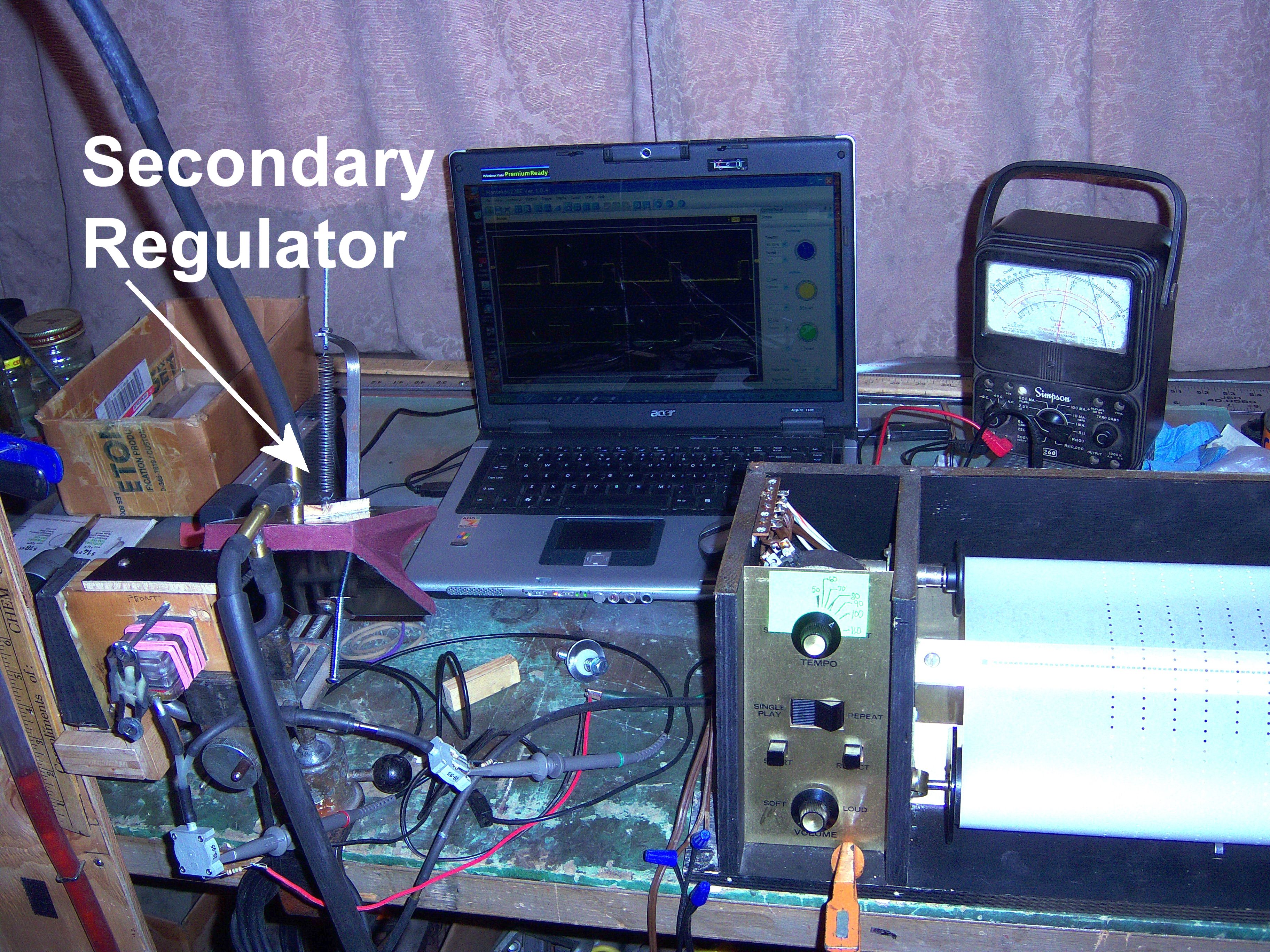
(5" WC with 10 ft of tubing at 8-9 Hz) Let me start by saying that there's no easy way to interpret the results of these tests, but I'll try.
First, we need to understand what's happening. After literally hundreds of tests with the 5th test jig, it was found that the most consistent results were obtained using 5" of vacuum, ten feet of trackerbar tubing (between the trackerbar and the valve block), and a repetition frequency of between eight and nine Hertz. Second, the variation in the repetition frequency, from eight to nine Hertz, is what happens normally when a test roll travels from 8-10 feet at a tempo of 80. The test roll has 54 perforation per foot. (For more information about the test roll, click here.) Third, the oscilloscope is set on the 50 ms (millisecond) range. What that means is that the time between each of the marks on the horizontal white line in the middle of the display represents 10 milliseconds. Fourth, each of the two probes of the oscilloscope is connected to a very sensitive vacuum sensing switch. Both switches are set to change state when there is a change of one inch of vacuum (1" WC). Fifth, the yellow line in the upper half of the display is associated with the atmosphere that enters the pouch well. As the perforation in the test roll passes over the trackerbar, atmosphere rushes down the ten foot length of trackerbar tubing and begins to 'fill up' the pouch well. (For more information about what actually happens when a signal from the trackerbar triggers a valve to change state -click here.) When the vacuum level inside the pouch well decreases by one inch (1" WC), the sensing switch changes state. In the case of the 'pouch switch', the switch is wired such that it comes 'on' when the vacuum level in the pouch well goes from 5" WC to 4" WC. And, it remains 'on' until the vacuum level increase to above 4" WC. The vacuum level inside the pouch well never goes down to 'zero' because the bleed is constantly supplying vacuum to (or attempting to suck the air out of) the pouch well. So, theoretically speaking, the waveform you see in the display represents the amount of time that the pouch is inflated and the valve is in the 'on' position. Sixth, the green line in the lower half of the display is associated with the striker pneumatic (or note bellow). As the valve changes state, the atmosphere is sucked out of the bellows, causing it to collapse. In this case, the sensor switch is wired such that it changes state as soon as there is at least one inch of vacuum (1" WC) inside the bellow. And, the switch remains 'on' until the vacuum level decreases to below 1" WC.
One of the things that might be somewhat confusing is the obvious differences between the pouch waveform and the bellows waveform. As can be easily seen, pouch waveform is consistently shorter in duration than the bellows waveform. There are two reasons for this. First, the instant that the valve 'begins' to change state, the vacuum starts sucking the air out of the bellow. And, assuming that the bellows and the exhaust valve facing are both air-tight, the vacuum keeps sucking the air out of the bellows until it is fully collapsed. Or, it will continue sucking the atmosphere out of the bellows until the valve changes state. Second, as the valve is changing state to the 'off' position, the vacuum is still being applied to the bellow. And, it continues being applied to the bellows until the valve is fully closed. Also, from the time that the valve begins changing back to the 'off' position until the valve is fully closed, atmosphere starts entering the bellow. If you could see this action in slow motion, you'd see that the atmosphere starts entering the bellows through a tiny opening, at the moment the valve beings to change state, to a larger opening, as the valve finishes changing state. This is often referred to as the valves "transient" time. However, this is only about half of the picture. The understand the whole picture, we need to consider a few other factors. First, the cubic area of the pouch well and the bellows are significantly different. Without getting into any heavy mathematics, suffice it to say that the average bellows is 7-10 times larger in cubic area than the average pouch well. So, it would seem to stand to reason that it will take longer for the atmosphere to fill the bellows than it will for the vacuum to suck the atmosphere out of the pouch well. But, in reality, that's not the case. That's because the opening through which the atmosphere enters the bellows (the exhaust valve port) is many times larger than the bleed, which sucks the atmosphere out of the pouch well. So, why does the vacuum remain in the bellows for such a longer time? The simple answer is 'gravity'. Once the valve changes state and the atmosphere is no longer being sucked out of the bellows, the bellows has to return to its full open position. Under normal circumstances, there are three forces working to open the bellow. One has to do with the bellows cloth which has a naturally 'springy' nature. In other words, by nature the bellows wants to open on its own. (Anyone who has built bellows understands this fact.) Secondly, due to the way the bellows is situated in the player mechanism, the movable board wants to 'fall' down (or open) because it has mass (or weight). In this case, the force of gravity is doing the work. Third, there is the weight of the piano action pushing down on the bellow. As explained earlier in this treatise, the average grams weight touch of a piano action is about 50 grams. So, as the piano action returns to its resting point, it exerts pressure on the movable bellows board. These three forces, working together at the same time, actually "create" vacuum within the bellow. NOTE: In the case of the test jig, a spring-loaded bellows is being used to simulate the three forces. So, it is the action of the spring, forcing the bellows to open, that creates the vacuum. IN essence, it's like a miniature reservoir bellows which has 'stored energy'. As a result of the above mentioned forces, the maximum repetition rate of all 'upright' player piano actions is limited by the length of time it takes for the bellows to go from the open state to the collapsed state and back to the open state. That's because the piano action can't 'reset' until the bellows opens again. In a 'grand' piano, this length of time is significantly less because of the design of the piano action. But, that's a whole other topic. Throughout all of the testing that I did, it was consistently obvious that the pouch and valve were not the limiting factor in the repetitive capability of the mechanism. In fact, I could easily get the pouch and valve to operate five times faster than the bellows, even when I had the spring tension on the bellows set to 160 grams.
If you're still with me, let's look at the video of the eight test pouches. I would encourage you to stop the video and closely examine the waveforms for each of the pouches. While the differences between them might seem relatively slight, remember that the waveform you're seeing in the upper trace represent the length of time it takes for the atmosphere to begin filling the pouch well when the perforation in the music roll opens the hole in the trackerbar plus the time it takes the vacuum to suck the atmosphere back out of the well after the perforation has past. Also, the lower trace represents the length of time it takes for the vacuum to start sucking the air out of the bellows once the valve begins to change state plus the time it takes for the bellows to return to its relaxed position. Also, since everything except the pouch is identical in each test, the differences you are seeing represent the differences in the way the pouch is performing. We'll get deeper into that after the video. I have purposely increased the size of the viewing area so you can see the details more clearly.
Now we'll take each pouch one at a time and explain what the video shows. The first two segments show pouch #6 at two difference repetition rates. The first at a tempo of 80 and the second at a tempo of 100. It's important to note that all of the subsequent segments show the operation of a pouch/valve/bellows at a tempo of 100, at approximately 8-9 Hertz. The actual frequency can be seen in the bottom portion of the oscilloscope screen. It is labeled 'Output' Ch1, Frequency. Notice that at a frequency of 9.1Hz, the width of the pouch waveform (PW), which we'll call #6-PWF, has a pulse width of just under 20 milliseconds (20ms) and the bellows waveform (BW), which we'll call #6-BWF, has a pulse width of 75ms. This means that with the #6 pouch, it takes about almost four times longer for the bellows to complete a cycle than it does for the pouch to complete a cycle. Later it will be explained how this information is used to compare the sensitivity and repetitive capability of the various pouches. The third segment in the video is pouch #1, which starts out at a frequency of 7.97Hz (8Hz). The first thing you notice is the odd spike in the bellows waveform (BW) that occurs 10ms before the main portion of the waveform. What this indicates is that the valve is not changing state swiftly. As a result, the vacuum level in the bellows starts to increase but then decreases as the valve is changing state. Once it finishes changing state, the vacuum level goes up again. There are only two possibilities that explain why the valve would be slow to change state. One, the pouch is a little stiff. Two, the pouch is leaking. However, as noted by the shorter length of the waveform, it is more logical to conclude that the problem is, in this case, leakage. That's because a pouch that leaks will always inflate more slowly and deflate more rapidly. And the evidence that the pouch is deflating more rapidly is shown in the fact that the length of the waveform is only about 70ms in duration.
The aging process started in October 2016 and continued through the end of January 2017 -a period of three months. The procedure was quite simple. For 24 hours, the pouches were put into a seated container and left in a freezer with a temperature of 20 degrees Fahrenheit. Then, for the next 24 hours they were put in a 'hot box' with a temperature of 140 degrees Fahrenheit. As was reported in the Mechanical Music Digest in early January 2017 in an article titled Testing Pouch Sealants, "Regardless of the sealant that is on the leather, the leather (for lack of a better term) 'shrinks'". Also, "The test pouch that wasn't sealed has the least amount of shrinkage." NOTE!!! 100 ms equals 10 HZ (cycles per second). drill #48 (0.0755" diameter). Amendment 9/6/16: In the JT Pouch Test Roll, there are 54 perforations in one foot of paper. So, at a Tempo of 80 (which is the recommended test speed), the frequency of the perforations is 7.2 Hz. At 140, the frequency is 12.6 Hz. In the Ampico Test Roll, a 0.0755" OD hole occurs every 125 ms at a Tempo of 80 (8 ft./minute equals 625 ms/inch of travel). In the Repetition Test, there are 5 perforations per inch, followed by a 1/4" perforation. Therefore, the repetition rate of the 5 perforations is 8 Hz (or 8 cycles/sec), with perforations occurring every 200 ms. Based of the diameter of the perforation, the duration of each pulse (which allows atmosphere into the pouch well to inflate the pouch and turn the valve 'on') is 75 ms. That leaves 125 ms for the valve to reset. Theoretically speaking, this fact refutes the claim that it takes 3-4 times longer for a valve to turn 'off' than it does for the valve to turn 'on'. More tests to follow..... To fully understand how a valve in a player piano works, please read "How the Notes Play" To return to where you were -click here. "CAUTION" - Always adjust No.1 Intensity as low as possible." Approximately 2 grams of Dow Corning 111 was thinned with approximately 1 fluid ounce (two tablespoons) of Gentech. Gentech, which is manufactured by Reliance Speciality Products, Inc., is an excellent replacement thinner for trichloroethylene. However, as with all industrial solvents, it must be used with reasonable precautions. During initial testing, it was discovered that all commercially available lacquer thinners are NOT the same. The first pouch that was sealed with a mixture of DC111 and lacquer thinner performed very badly -even after three applications of a solution, that was prepared according to the instructions given by Craig Brougher. Further research revealed that the lacquer thinner used to thin DC111 must contain Xylene. In Craig's own words' "I think good lacquer thinner is going to have some Xylene in it." The thinner that was initially used contained Acetone, Ethyl Acetate, Methanol, Petroleum Distillates, and Toluene. It produced a mixture that contained so little DC111, that there was very little difference between the sealed pouch and the unsealed pouch in terms of air-tightness. However, the mixture made the pouch leather much stiffer. Go Back to Previous Location The DC111/Gentech mixture performed remarkably better. In fact, in a single application of the mixture, it sealed the leather better than any of the other sealants without having hardly any effect on the stiffness of the leather. (I am still trying to locate a lacquer thinner that contains the 'ingredients' that are in the stuff Craig uses.) FYI, Gentech is not a commercially available product. According to the manufacturer, Gentech is a "critical cleaning solvent for vapor degreasing and cold wipe". NOTE: January 21, 2018: It has come to our attention that due to the changes in the chemical composition of modern lacquer thinner, Dow Corning 111 does not become homogeneous. To correct this problem, mix two grams of 111 with 1 fl.oz. of Xylene (or Zylol) and 1 fl. oz. of M.E.K. It will take about an hour for the grease to completely homogenized in the mixture -when well shaken at 15-minute intervals. For reference sake, 1 fl.oz. of liquid equals 2 tablespoons of liquid. NOTE: Your regular tableware tablespoon is NOT and actual tablespoon in size. Also, be sure to measure chemicals in metal or glass. Do not use plastic measuring devices. Go Back to Previous Location
OTHER NOTES: Improper regulation, let-off and key dip, or even too-soft hammer voicing can also make the piano feel "heavy" because it requires more effort for a player to get the sound they expect. I've even seen a customer insist their grand action was too heavy when in reality it was way too light (less than 30 grams down weight where 48 to 53 grams is normal) which caused the action to feel sluggish because there was insufficient up weight to quickly reset the action back to the proper rest position when a note was released. If the action is properly repaired and regulated, then a too-heavy or uneven down weight is probably caused by too-heavy hammers or improper key lever weighting. As Robbie pointed out, new replacement hammers are usually heavier than the originals, sometimes by as much as 2-5 grams, which with the action leverage can make the touch weight as much as 10-30 grams too heavy, often unevenly from bass to treble.
|
| Player Piano Reference Materials - Click Here |

![]() ..To
The Top of this Page . . . . . . . . . . .
..To
The Top of this Page . . . . . . . . . . . ![]() ..To The HOME Page
..To The HOME Page
|
Since "Player-Care" is an internet business, I prefer that we correspond via E-Mail (click here to fill out the 'Request Form'). However, if I'm not in the middle of some other activity, you can reach me at 732-840-8787. But please understand that during the hours from 8AM-5PM EST (Mon-Sat), I'm generally quite busy. So, I probably won't answer the phone. If you get the answering machine, please leave a detailed message stating the reason for your call. Also, repeat your name and phone number clearly and distinctly. By necessity, I prioritize everything in my life. And, if you call and just leave your name and number, and ask me to call you back, it might be a day or two before I return your call. Why? Because I don't know why you want me to call and I might not be prepared to assist you in an effective and efficient manner. If you leave me an E-Mail address (which I prefer), spell it out phonetically. The more you do to help me, the more I can help you in return. Don't rush. You have four minutes to record your message. |
|
407 19th Ave, Brick, NJ, 08724 Phone Number 732-840-8787 (Voicemail Only, No Texts) |
