
|

|

|
|
|
|
|
| Home | Manuals | Supplies | Search | Consult | Contact | Testing | Service |
|
1. Introduction. In 1986, as a newcomer to the field of mechanical music, the author (Paul Rumpf) rebuilt his first foot pumped player. The action was Simplex. The cloth used was made by Archer Rubber in Massachusetts. The player performed beautifully in the sense that the player was able to play reliably at 4 inches of vacuum and would play, albeit, erratically, at 3.5 inch. The expression available by careful pedaling was quite musical. The next unit to be rebuilt had a H.C. Bay action. When reassembled and tested, it required 6 to 7 inches of vacuum to play reliably. By comparison with the Simplex, it was dreadful. It transpired that the original Archer Rubber material was not available at that time, and had been substituted by a local Australian made material. The base cloth was described as 80/80 shirt material. (See Aussie 1 in the table in Para. 8) The poor performance suggested a line of investigation to determine those factors, which led to a reliable playing performance at low levels of vacuum. At this time, another new Australian manufacturer expressed interest in producing this light weight rubber coated cloth. I arrived on the scene and we worked together to develop a suitable material. 2. Investigation. In the book, "Player Piano Servicing and Rebuilding" by Arthur Reblitz, the recovering of small pneumatics (pneumatic motors), is described. On page 70, Illustration 5.66, the caption says; "A completed pneumatic. The cloth is perfectly smooth and unwrinkled all the way around, the edges are trimmed neatly without any gouges in the wood or rough edges of glue, and the pneumatic easily falls open and shut under its' own weight" (see Ref. 2.). In mentioning this performance requirement with a couple of rebuilders, their response was, "I can never get them to do that." It was concluded that modern rubberised cloth manufacturers, effectively had no product specification which would allow a manufacturing in-process set of criteria. Further, to expect a pneumatic cloth manufacturer to have to make a small note playing pneumatic and test it for performance, was unrealistic. How possible was it then, that a cloth coating manufacturer could have a manufacturing and a test method that was relevant to him, but correlated with the required pianola performance. The purpose of this paper is to attempt to generate a manufacturing specification for any manufacturer to produce high performance rubberized cloth for covering small note playing pneumatics 3. Investigation of 'Original' Materials. Many samples of original cloth were examined for the weave characteristic, and the way in which the rubber compound was applied. The weave and the weight of thread used was obviously a key parameter. In textile manufacture and other woven products, there is a parameter known as picks, and the pick density is ‘picks per inch’. To measure this parameter, a device called a pick glass is used. This has a half inch, or one inch, square window section, which is placed over the cloth, and through an attached lens, one can count the number of visible threads in the half inch or one inch window. The threads are counted in both the machine direction (MD), and the cross direction (CD). Table of original cloth samples examined
Comment:
4. Cloth manufacture. Production of woven cloth produces a continuous linear product which has two directions; the machine direction (MD), which is the direction the product moves during production, and the cross direction (CD), which is the direction perpendicular to the machine direction. With a weaving process, the cross direction threads are produced by a shuttle which moves in the cross direction. The cross direction has different dynamics to the machine direction wherein the CD thread is subject to high acceleration as the shuttled traverses from side to side. Ultimately, the production throughput is limited by the number of times per unit of time, that the shuttle goes from side to side. As the shuttle speeds are forced, by machine design and economics, to be as high as possible, the possibility of thread breakage also increases, and a broken cross thread forces the machine to halt while the thread is repaired. As the thread weight or ‘thread count’ is reduced, the likelihood of thread breakage increases. One way of adjusting the material design, is to make the machine direction threads rather fine, and to reduce the number of cross direction threads. In that way, the production speed is increased for the same shuttle speed. The effect on the cloth material is that it behaves differently between the MD and CD. (see ref 1) 5. Cloth and pneumatic motor design parameters. As a first step, the mechanical force developed by the pneumatic motor had to be established. The work, ‘Mechanical Forces Developed by Pneumatic Motors’ has been published by this author, and is available on the MMD website. That paper showed that as a pneumatic gradually closes under vacuum, the force developed gradually reduces, compared to the force of the fully open pneumatic. What has been universally observed by those involved, is that a newly covered pneumatic should close under its own weight, but seldom does. (see ref 2). This is because the inherent forces in the cloth, which resist closure, are too great to allow the intrinsic weight of the pneumatic and its wood components, to fully close the pneumatic. The closing force is therefore a parameter of interest to quantify the effect of different pneumatic cloth materials. The ‘closing force’ in the table is the force required to hold the moveable board under gravity, at a point which is 90% closed. It is a rough and ready measure, and subject to some variation. As an aside, note that the cushion stop in Illus. 5.51 (Ref 1), is attached on the stationary board rather than the moving board. The reason for this to minimize the mass of the moving board. 6. Bending forces. It is known from other work in the authors experience, that when thin materials are bent and/or folded, then the force required to fold the crease into an ever reducing radius of curvature requires increasingly higher force. For the problem here, of achieving a small closing force, it is axiomatic that the material should be as thin as possible. A few simple experiments showed that the closing force of a pneumatic with plain un-coated cotton cloth was effectively due to the weight of the moving board. This showed that the closing force was going to be entirely due to the rubber coating, its' thickness, and stiffness. 7. Pinholes and air consumption 7.1 Pneumatic motor air consumption. In any discussion of rubberized cloth, the question of pinholes arises, and how many are acceptable. When a pneumatic motor is at rest, it is disconnected from the vacuum supply and it is immaterial whether it has a gas-tight coating on the cloth or not. However, when the pneumatic is exhausted, then gas leakage through the cloth is a performance consideration. The table below shows the effective internal volume of three, different, pneumatics.
Note that these values are the effective air volume change as the pneumatic is exhausted. The volume change is taken to be the internal air volume as the pneumatic goes from 90% open to 10% open. The width(W) is the width of the moving board; the height(H) is the width of the pneumatic cloth MINUS the thickness of the wood parts of the pneumatic at the open end, the length(L) is the distance from the hinge to the open end of the pneumatic. Each and every time the pneumatic closes, this is the volume of air that must be extracted. There is additional air to be removed as well. This air, is the volume of air between the sealing face of the valve button, and the pneumatic. In the Simplex valve, this volume is rather small because of the unit valve design and the small air channels in the pneumatic body. The Standard has a greater air volume because of the extended channel between the top of the valve on its mounting board and the channel (pipe) to the pneumatic mounting point. Similar comments would apply to the Aeolian. In Ref 3, that author, says, 'the Aeolian action operates on a relatively low volume of suction'. The table above shows that. 7.2 Air bleeds and air consumption. As part of the pouch system, there is an air bleed across the diaphragm. With no notes playing, there is no air flowing through the bleed. In the Durrell Armstrong PPCo catalog, P 40 refers to bleed sizes. For a leak free rubber diaphragm, a bleed size of #64 is used, but for pouch leather, a size of #70 (approx.). Air flow calculations through small holes is a notoriously difficult area of engineering. I used a formula from TLV. See ref 4. The pressures are: Inlet pressure: 760.0 mm Outlet pressure: 750.66 mm at 5" water Outlet pressure: 722.6 mm at 20" water For these pressures, the table shows the flow rate for various bleed sizes, and a pinhole.
This data shows that a #65 bleed uses about as much air in one second as the amount of air used to close a pneumatic. 7.3 Air leaks due to pinholes. This section is best described as an educated guess. Nevertheless, it is necessary to get a feeling for the amount of air passing through a pin hole. To do this we have to 'guesstimate' the size of the pinhole. The cloth weave used originally was at least 100 TPI, so we can attempt to determine reasonable dimensions for a pin hole. It will not be bigger than the interstitial space between the threads. So how big is this mysterious space? A sample of Australian made coated cloth was photographed through an optical viewer. The cloth weave was 120 x 90. (Aussie 3 in the table below). The thread spacing is: vertical 1"/90 = 0.011". By scaling off the screen, the rubber part is about .0046 x .009", giving an effective circular diameter of about 0.00725 inch. Rough and ready, but good for purpose. 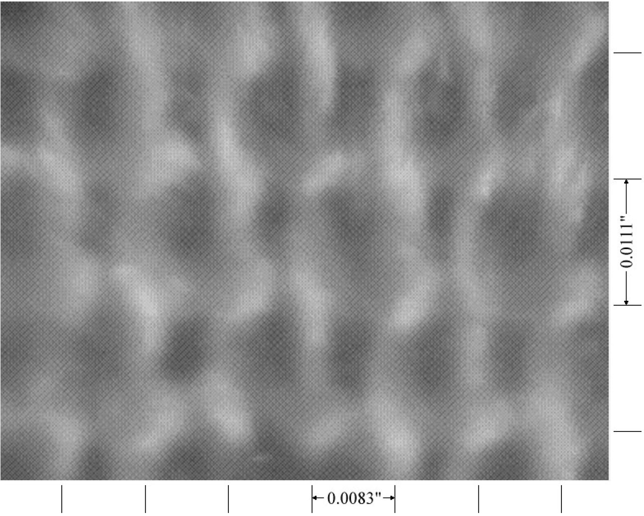
Using a bleed hole size of 0.00725" (0.184mm) in the formula shows the air leakage @ 20 inches of water, to be 0.123 cm3 per minute, or 0.002 cm3 per second. The flow rate through this pinhole is only 1/1000th of that passing through the pouch venting bleed. There would need to be 30,000 pinholes in the exposed cloth for the pin hole leakage to be equal to the bleed. Looking at these numbers and the relative significance, it can be seen that pinholes are not very significant a factor in vacuum leakage. Having said this, it is possible to produce cloth with a very low pin hole count. In a sample of cloth returned to the manufacturer because of 'too many pinholes', the size of the sample was 252 x 54 mm. That is an area of 136 cm2 . The sample showed about 16 pinholes. That is about 0.12 hole per cm square. Given that 2/3 of the pinholes are going to be covered by wood and glue, the effective pinhole density is 0.04 pin holes per cm square. Given an exposed cloth area of 30 cm2 and this pinhole density, a typical Aeolian pneumatic would have 1.04 holes per pneumatic. The conclusion that the author comes to is that manufacturers and purchasers of cloth have needlessly striven for pinhole free cloth, and at the same time have destroyed the performance characteristics of the pneumatic cloth by stiffening the cloth excessively. 8. Production experience. The author had no real input to the rubber formulation; this was left to the manufacturer. The role of the author was to advise the product use requirement. Matters of rubber formulation, filler specification, aging specifications were not canvassed. The sample Aussie 3 was a good quality material, fine rubber, small thickness, and low closing force. Production date was around 1989. Table of modern and experimental cloth samples.
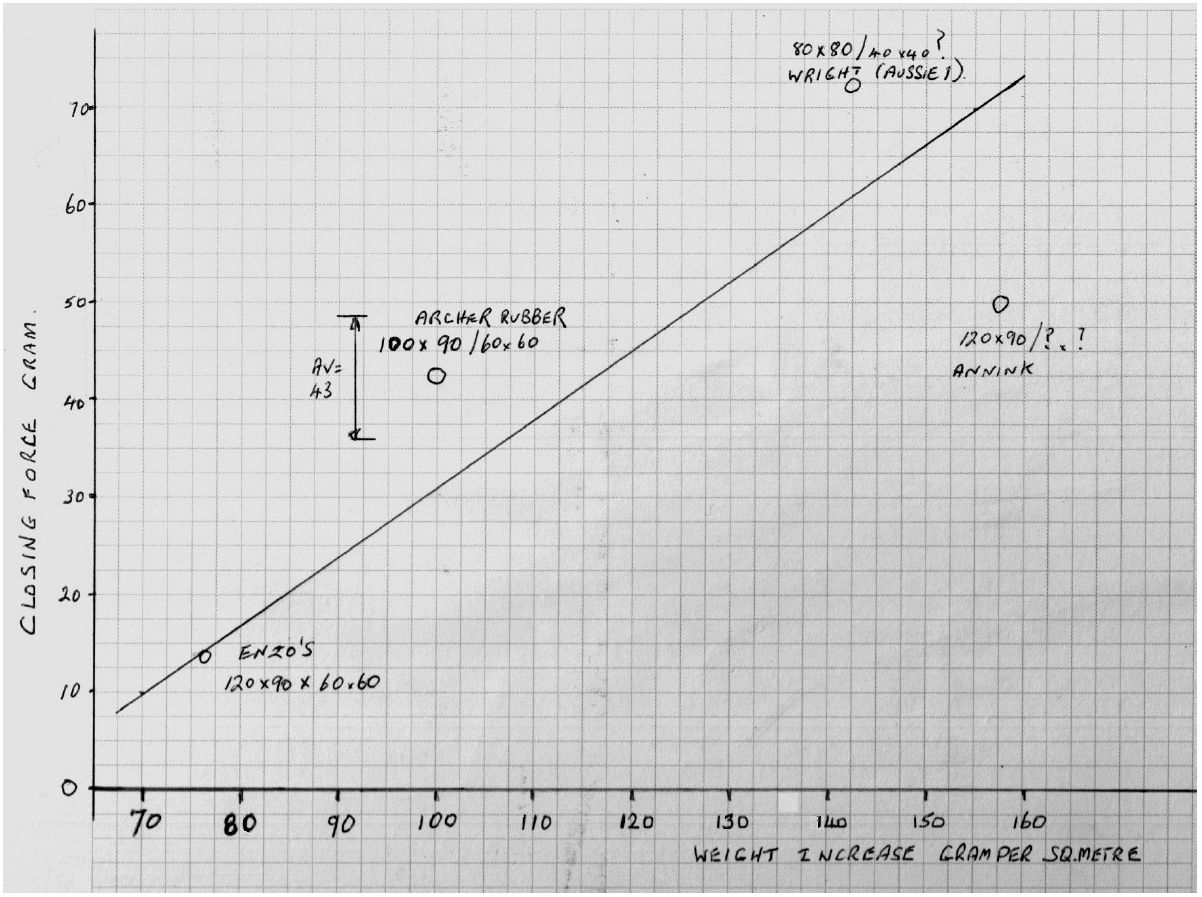
* indicates the sample data used to prepare the graph of 'Closing Force'. NOTE: The table results were actually determined from a coated cloth sample of size 30 mm x 295 mm. This sample was then glued to a Standard action pneumatic, to measure the closing force. The manufacturer of the Aussie 1 sample, advised that he used 6 coatings of rubber to produce the cloth. This was the cloth used to repair the HC Bay action. Note the weight/weight increase of the cloth. During the development investigations, production trials were carried out on cloth made for sale to pianola re-builders. In one case, cloth was returned to the manufacturer because it had pinholes. There is no real specification for pinholes except that; "we don’t want any". Pinholes occur because the interstitial space between threads is large and the rubber cannot breach the gap and seal over the space. In manufacture, the cloth is run through the coating process a number of times. Examination of the weight of various cloth samples suggests that common practice is to apply 3 to 4 coating layers. With a coarse weave, say 80/80, the interstitial space is large and more rubber is required to eliminate pinholes. (See 'Aussie 1' sample). Also, the lack of support given to the rubber in the space, is likely to allow fractures in the rubber over time, with use. The use of filler materials in the rubber can also lead to fracture of the rubber coating due to bits of filler falling out of the coating. These factors lead to the prime requirement for a finely woven cloth, to be coated with a thin rubber and, if fillers are used in the rubber, for the fillers to be finely ground. All this implies an expensive material. Due to the way that the pneumatic cloth is used in covering small pneumatic motors, the glued edges contribute no leakage. This effect is best seen from the covering of a Simplex unit pneumatic. The cloth area required initially, is 85.7cm2 (252mm x 34 mm), and the cloth area exposed to vacuum is 26.1cm. The percentage of cloth that is exposed to vacuum is 30.4 %. The remaining 70% is covered with glue. For Aeolian types, the initial cloth area is; Initial size is 2.6 x 30.0 cm = 78 cm2. The area exposed to vacuum is 22.5 cm2. The percentage of initial cloth exposed to vacuum is then, is 29%. In practice, the effective pinhole count is only 30%, or 1/3rd of the number of pinholes visible in the raw/new coated cloth. The Standard type will have a similar pin-hole reduction factor. 9. Preparing bulk material for recovering pneumatics. The manufacturing process is essentially a screening process where semi-liquid rubber is squeegeed onto the cloth by a scraping straight edge. The material to be coated is passed around an accurately machined flat roller surface with a blade running over the coated side of the cloth. The accuracy of the machining and the gap between the cloth and the blade determines the coating thickness. Across the width of the material, there would/could be variation in the coating thickness. By cutting the length of the cloth in the machine direction there could be differences in coating thickness between pieces used for each pneumatic. However, if the cloth pieces were taken across the width of the cloth, any variation in coating thickness would be averaged. It is recommended therefore, to tear cloth pieces across the width of the bulk material. 10. Closing force.
 11. Non-natural cloths. During the investigation, many samples were obtained from a manufacturer in Taiwan. The base cloth was a nylon material, and the covering was polyurethane. Measurements of the material indicated it would perform well, but this turned out to be not the case. The closing forces were quite high, and the difficulty of gluing was a real problem. Some of this material was used to recover a set of Duo-Art intensity setting bellows. The performance was OK but this application is no-where near as critical as the pneumatic motor performance requirement. This kind of material is not recommended for covering small note playing pneumatics. 12. Summary and Conclusion. This paper records the results of an investigation into lightweight rubber coated cloth for use in Pianola note playing pneumatic motors. The recommendation for manufacture of suitable material is
About the author. Paul Rumpf was born in 1942 in Melbourne, Australia, on the day of the Battle for the Coral Sea. After graduating in Communications Engineering, he worked for Philips Electrical as a development engineer for radio and television receiver components. A long period followed in the telephone cable manufacturing industry. After retiring in 1995, He worked his farm raising beef cattle and developing a vineyard and winery. Since retiring from the farm life in 2017, Paul has turned his attention to finally cleaning up all unfinished work. This paper is one such project. April 4, 2022
Ref 1; Arthur Reblitz, Player Piano Servicing and Rebuilding, page 67. Ref 2; Arthur Reblitz, Player Piano Servicing and Rebuilding, page 70, Illus. 5-66 Ref 3; Arthur Reblitz, Player Piano Servicing and Rebuilding, page 99 Ref 4; https://www.tlv.com/global/AU/calculator/air-flow-rate-through-orifice.html This article appeared in the Mechanical Music Digest on April 21, 2022. It is being presented here with the permission of both the author and the MMDigest Regarding copyright, the author copyright remains with Paul Rumpf. Compilation copyright 2022 is held by Jody Kravitz (Mechanical Music Digest) and is hereby licensed to John A Tuttle for re-publication at the Player-Care.com web wite. The article must not be posted elsewhere without the permission of the author and the MMDigest. |
|
Since "Player-Care" is an internet business, I prefer that we correspond via E-Mail (click here to fill out the 'Request Form'). However, if I'm not in the middle of some other activity, you can reach me at 732-840-8787. But please understand that during the hours from 8AM-5PM EST (Mon-Sat), I'm generally quite busy. So, I probably won't answer the phone. If you get the answering machine, please leave a detailed message stating the reason for your call. Also, repeat your name and phone number clearly and distinctly. By necessity, I prioritize everything in my life. And, if you call and just leave your name and number, and ask me to call you back, it might be a day or two before I return your call. Why? Because I don't know why you want me to call and I might not be prepared to assist you in an effective and efficient manner. If you leave me an E-Mail address (which I prefer), spell it out phonetically. The more you do to help me, the more I can help you in return. Don't rush. You have four minutes to record your message. |
|
407 19th Ave, Brick, NJ, 08724 Phone Number 732-840-8787 (Voicemail Only, No Texts) |
