
|

|

|
|
|
|
|
| Home | Manuals | Supplies | Search | Consult | Contact | Testing | Service |
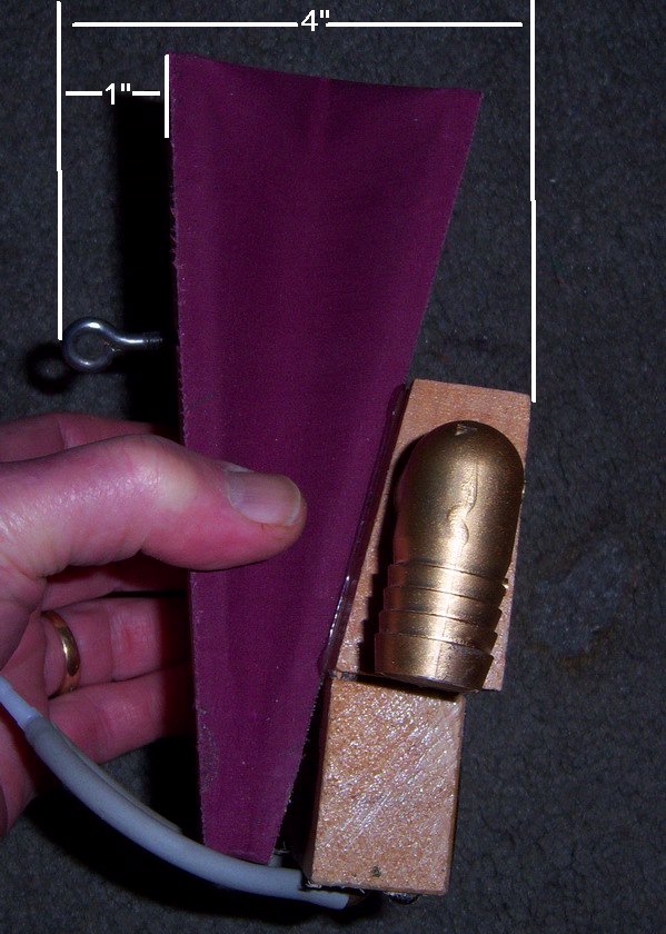
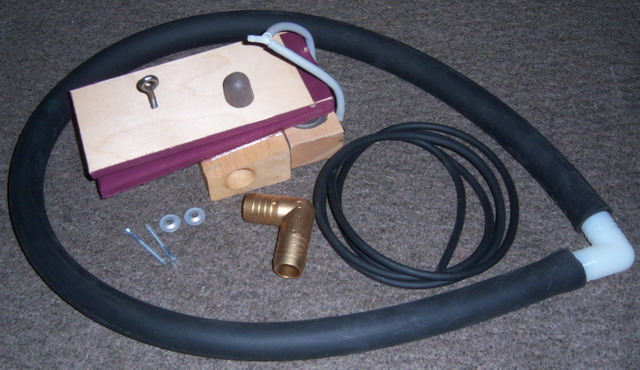 If you have any questions concerning the installation of this device, don't hesitate to call or write. This device has been redesigned to allow for the insertion of the 3/4" vacuum supply elbow on either side of the device. Therefore, a plug is supplied to plug the opposite hole in the device. Any glue or epoxy (not included in the kit) can be used to secure the plug in place as long as the seal is air-tight. Also, the kit now includes a 2 ft. piece of ladder chain to connect the device to the Play/Rewind lever or the Transmission. This pneumatic unit may be mounted in most any position, and can serve other purposes, in addition to it's most common usage as a rewind shift pneumatic. On electrified players, the valves respond to the rewind holes cut at the end of all the new Q-R-S rolls. The pneumatic shifts the spool box gears and other functions. This is automatically done, rather than requiring you to be on hand to shift the Reroll lever manually. Since the highest and lowest three playing notes have not been used for playing notes on Q-R-S rolls in over forty years, connect the small tube for the rewind device to one of these playing notes (#86 or #87 is recommended) at the trackerbar. Normally, this requires that you disconnect the note tubing which goes from the tracker bar to the "live" note on the pneumatic stack. If your trackerbar tubing is rubber, you can cut the tubing near where it connects to the stack, and use the small 5/32" brass nipple (comes with the reroll device) to connect the tube coming from the trackerbar to the tube going to the reroll device. If your trackerbar tubing is lead, connect the hose going to the reroll device to the severed lead tube. Be sure to re-open the end of the lead tubing where it was pinched when it was cut. Also, be sure and plug the disconnected note tube leading to the stack. If the tubing is rubber, you can simply tie a knot in the piece of tubing that goes to the stack. If it's lead, you can fold the tubing over on itself, and pinch the fold tightly with pliers. For the cleanest looking job, it is recommended that you remove the tubing at the trackerbar and connect the tubing, from the rewind device, directly to the nipple on the trackerbar. If in doubt, please contact me via email. There is no certain place or position for mounting this pneumatic. This is your first consideration and decision to be made; as will be noted by examining the transmission frame. Most gears shift to the right for Play and left for Reroll. This is actuated by an upright shifting lever on the transmission frame that pivots, so that the lower part of this leverage either attaches to a metal rod leading away from the spool box to the right, or in some cases, to the right, for an adjacent lever right in the spoolbox. Otherwise, the linkage leading away from the spoolbox goes to linkage of a vertical rod which connects to a manual shift lever on the key slip and to move positions of the pump cut-off and motor by-pass valve. The manual shift lever being located in the spoolbox indicates these functions are carried out through pneumatic action via a signal valve opening, on or below the transmission frame. There is usually some space on the right side of the piano case, which allows mounting of this pneumatic, directly to the left of the pneumatic motor. Sometimes, the supply hose for this motor must be rerouted slightly aside to make the necessary room. In many cases the rod coming from the transmission frame will terminate at a crank just above the cheek block and head downwards. In most cases, a 'pull' on this rod would shift the transmission to Rewind. However, in some transmissions, such as the "Standard Action" or the "Autopiano", compound leverage is used which reverses the need; to a push being required instead. The #916 pneumatic can either push or pull. For a push: a finger (a scrap stick of wood about 5" x 3/4" x 3/8") is screwed across the hinge end of the pneumatic; as the open end of the pneumatic closes, this finger levers across the hinge. The length of the finger extending past the hinge will determine the stroke. If the hole in this finger, which attaches to the push rod, is half the distance from the hinge as the pneumatic is in total length, the rod will move one inch in the opposite direction, for each two inches closing of the pneumatic. This compound leverage is desirable, because it doubles the power. By the same logic, this finger attached to the open end of a pneumatic decreases power, because it's much farther away from the hinge end, when used for the purpose of giving a pull. However, to get the line pulling low enough, it may be necessary to add a finger over the open end. The further open the starting position of the pneumatic to exert force, the more power it has. Therefore, fulfillment of it's function coincides with the position of the internal stop adjustment, allowed by the stop screw. If the more conventional requirements of a pull to the right is required to shift the gears, this could be accomplished by attaching a string or wire going from the transmission to the pneumatic, moving under the pneumatic motor. For some cases, this easy means might be possible. Rather than run a separate attachment to the transmission shift lever from the pneumatic, the existing linkage rod running to the right side, whether push or pull, might be better attached by the pneumatic with a forked finger downward from the pneumatic to ride over the rod, with a set-screw collar for the forked finger to pull or push against. In many cases, there is no space on the right side of the piano case to mount the #916 pneumatic. It is best then, to immediately consider the opposite side of the piano case, which is nearly always vacant. Although, being much further away, there is the additional problem of crossing behind or over the spoolbox to reach the connection point of the transmission shifting lever. In this case, a long rigid steel rod, of at least 1/8" diameter could be held at the rear of the spoolbox, behind the transmission, by a guide or bearing which holds such a rod in place, and allows it to travel hack and forth horizontally, and also to have this rod bent at a right angle to come into the transmission shift lever from the rear, and push the shifting lever to the right side from a position to the left of it. (Or the opposite of this, depending on the direction required to shift the lever to rewind position.) In a few cases, by attachment to one of these rods moved by the manual key-slip shift levers, which are located under the key bed, might be considered. It doesn't matter where the engagement is made -directly on to the transmission frame, or the furthest point- the same amount of load or friction is incurred. There is usually not enough space in the areas that would be best suited for direct connection, and would require further cranks and linkage. The #916 pneumatic is basically designed for the mounting in a vertical position, however upward push can be had by placing a right angle bracket onto the pneumatic with a bend directly over the hinge end of the pneumatic. CONNECTING TO THE VACUUM SUPPLY Vacuum represents a non-mechanical source of power transfer in the same vain that electricity is to an electric motor or solenoid force. On one hand you have the task of how to apply the power to moving something; and on the other, where to get that power ultimately. The 3/4" vacuum hose to supply the #916 pneumatic, is perhaps a bit large, since the main supply to the 88 pneumatic note valves is sometimes not much larger, but this size can more easily handle the problems of air friction or resistance. But even going to the unit valve blocks with small passageways, the air travel will speed up going through these restricted short passageways, relative to the movement through the larger supply hose. Otherwise, if the vacuum supply tube were the same size as these openings through the valves, there would be greater friction and slowing down of the movement in the smaller tube. The movement of the pneumatic would likewise tend to be more sluggish. Since the very response to operate this is keyed in by the reroll perforation across the tracker bar and is being cut off in almost the same instance by the pneumatic's own action, it is essential to have a swift action, or movement. The best place to connect the vacuum hose is to the reservoir on the right side of the exhauster assembly. This insures a strong full stroke of the pneumatic, which is essential for shifting the transmission from Play to Reroll in a smart fashion. In most cases, you can drill a 3/4" hole into the front of the right reservoir near the top right corner of the bellow. However, if the air motor governor is located on the front of the reservoir, pick a convenient location below the governor. Note: It's best to stay away from the edges of the bellows because as the reservoir collapses, the cloth draws into the inside of the bellows at the edges. This could feasibly restrict the vacuum flow to some extent if the cloth is covering the hole. Another option is to attach the vacuum hose to the stack. There's usually enough residual vacuum left in the pneumatic stack after it is shut off, which allows the full stroke of the pneumatic, which at the same time is responsible for cutting off this supply. It acts as sort of a reservoir, in the same way the flexible walls of the large 3/4" supply hose does, but obviously, to a much greater extent. It is advisable, if at all possible, to enter the end of the pneumatic stack for inserting the nipple to connect the supply for the #916 pneumatic. You must never connect into the pneumatic roll motor supply line. If you did, and this were set to play a slow tempo, there would not be enough vacuum in the line to do the extra work. However, in the case of mounting the rewind pneumatic near the motor, it would be as close to drill a hole in the end block of the pneumatic stack and insert a nipple for fitting in the 3/4" hose. Another place would be to insert a "Tee" fitting in the line that supplies the pneumatic stack from the pump. Perhaps the loud pedal pneumatic supply could likewise be teed into. THE BLEED Since all valves must have an equalizing bleed hole to reverse it's pouch action, this function, to remain effective, must remain clear. Normal maintenance of a player system requires a flushing of all these lines, from accumulation of dirt and lint, which is too large to pass through this tiny hole, and then be exhausted out of the system. Occasionally passing a nozzle of the vacuum cleaner after sweeping your rug, over the entire tracker bar, you will pull this out the same way it got in. A tracker bar pump will do the same thing. Handy, but takes more effort. For the purpose of cases that may allow the ultimate stoppage of this bleed, the lint could become too dense and matted to respond to pumping back out from the tracker bar. And in this case, will have to be poked through with a pin or needle, gaining access by removing one of the valve blocks. OTHER USES FOR THE #916 Since the /#916 pneumatic is of a large size, it very well can be used as a pneumatic for automatic loud pedal. Many player actions, in their economy, left out this follow-through, and the perforation for sustaining notes, which is cut on the left margin of most music rolls, passes silently over the tracker bar. It is desirable to have and it contributes to the musical performance. The only other alternative to the automatic loud pedal is to put this effect in by operating the hand lever. For a permanent solution: install the no. 916 pneumatic in a space situated between the harp and the iron pedal rod at the bottom (usually left side) of the piano. The iron pedal rod connects with a wooden dowel which runs up the side of the piano. Attach a stock no. 911 pneumatic finger across the hinge end of the pneumatic, and place the pneumatic in position on the floor of the piano with the hole in the finger spindled between the iron pedal lever and the end of the wood lift dowel, with the pneumatic open (bending the finger to attain position) press the manual pedal by your foot, to check the leverage position on finger. If the pneumatic must close too far, reposition finger to overhang the hinge further. If there is not a 5-1/2" space between the iron pedal rod and the harp, the wooden rod bearing of the pedal rod can usually be repositioned. 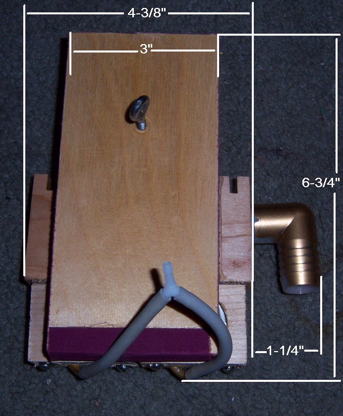
 |

![]() ..To
The Top of this Page . . . . . . . . . . .
..To
The Top of this Page . . . . . . . . . . . ![]() ..To The HOME Page
..To The HOME Page
|
Since "Player-Care" is an internet business, I prefer that we correspond via E-Mail (click here to fill out the 'Request Form'). However, if I'm not in the middle of some other activity, you can reach me at 732-840-8787. But please understand that during the hours from 8AM-5PM EST (Mon-Sat), I'm generally quite busy. So, I probably won't answer the phone. If you get the answering machine, please leave a detailed message stating the reason for your call. Also, repeat your name and phone number clearly and distinctly. By necessity, I prioritize everything in my life. And, if you call and just leave your name and number, and ask me to call you back, it might be a day or two before I return your call. Why? Because I don't know why you want me to call and I might not be prepared to assist you in an effective and efficient manner. If you leave me an E-Mail address (which I prefer), spell it out phonetically. The more you do to help me, the more I can help you in return. Don't rush. You have four minutes to record your message. |
|
407 19th Ave, Brick, NJ, 08724 Phone Number 732-840-8787 (Voicemail Only, No Texts) |
