
|

|

|
|
|
|
|
| Home | Manuals | Supplies | Search | Consult | Contact | Testing | Service |
|
The Air-Motor Governor Almost always, the easiest way to locate the air motor governor is to follow the hose, that's connected to the air motor, to where ever it leads. However, between the air motor and where the hose (or air channel) connects to the governor, you will always encounter a Tempo Control device of some kind. That's because the vacuum going to the Air Motor must pass through the Air Motor Governor before going through the Tempo Control. Another fact that is always true is that the Air Motor Governor has a bellows, whereas the Tempo Control does not. And, that bellows is spring-loaded. The bellows is also what is normally referred to as a 'medium size' bellow. In other words, it's smaller than a pump bellows or a reservoir bellows but larger than a note or striker bellow. Lastly, as a general rule, the Air Motor Governor is in close proximity to the Tempo Control device. In some cases, they are combined into a single device.
Problem 1: The air-motor speeds up when more pedal pressure is applied.
The problem is in the air-motor governor (or just 'governor') or the air-motor
control box. There are a few possible problems. 1) The material covering the governor bellows might be getting stiff
with age or leaking, preventing it from responding correctly to changing vacuum levels. If so,
recover the pneumatic with new cloth. 2) The return spring might be to tense, preventing the
governor from closing down fast enough or far enough.
(See adjustment procedure below) 3) The knife valve inside the governor might not be seating
correctly. (See below) 4) The fast re-roll port might not be closing all the way
when the unit is in 'Play'. (See below) 1) The return spring might be to loose, allowing the
governor to close down too much, starving the air-motor of vacuum.
(See adjustment procedure below) 2) The Stop screw is incorrectly adjusted. (See adjustment procedure below)
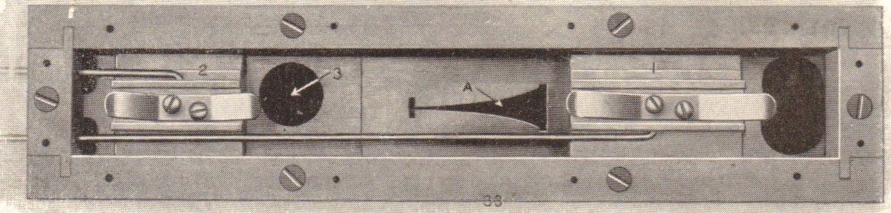
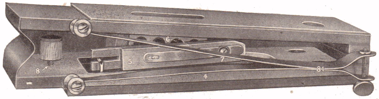 NOTE 1: Before adjusting the air motor governor, it is highly recommended that the physical location of the Tempo Slide Valve (1) be checked. This requires removing the access panel on the Tempo Control Box and physically examining the position of the sliding valve. When correctly adjusted, the tempo slide valve should just barely cover the tempo slot (A) completely when the tempo is set to '0', and it should just barely open the slot when the tempo is set to '10'. The slider should also open the slot completely when the tempo is set to '120' (or the fastest speed shown on the Tempo Indicator). If these conditions are not as described, corrective action should be taken. NOTE 2: There are dozens of different makes of tempo control boxes and air motor governors. However, the general proceedure for adjusting them is basically the same. If you cannot associate the components in the above diagrams with the components in your tempo control box and air motor governor, it is recommended that you get the service manual for your particular player system (click here). To test, have someone else pump the unit evenly and depress (or collapse, or close) the governor by hand. When depressed all the way, the motor should almost stop (with tempo set to 60-70). To insure that the stop screw (8), which prevents the governor from closing too far, is correctly adjusted, turn it 'out' one-half a turn at a time and test it again until the motor does stop when the bellows is fully closed. If the motor does stop when the bellows is collapsed fully, turn the adjustment back 'in' one-half turn. When adjusted correctly, the motor should just barely crawl when the vacuum level is high. If the motor never comes to a complete stop, the problem is in the adjustment of the fast re-roll valve (2) or with the knife valve (5) inside the governor. To eliminate the possibility of the fast re-roll valve as being the problem, open the control box and visually check the position on the fast re-roll valve while the unit is in the 'play' position. It must cover the air-port (3) 100%. Also check the integrity of the leather. It must be smooth and slightly flexible to make a good seal. Reassemble everything and test again. If the motor still fails to stop, the knife valve is the problem. Open the governor and inspect the surfaces of the knife valve. They must be smooth and make positive contact with each other. Rarely, the tension spring (7) needs to be tightened slightly to insure positive contact of the knife valve with the air port (6), but do not over-tighten the spring (7). Clean and re-graphite as necessary. Reassemble and test. If the motor STILL refuses to stop, there is a leak somewhere in the control box which is allowing vacuum to bypass all the above controls. Seek out and eliminate the leak. To adjust the governor once all of the problems have been eliminated, you need a Test Roll to calibrate the governor and the control box. As a preliminary adjustment. Set the tempo to "0". The motor should stop. Set it to "10", the roll should 'creep'. Set it to "70" and measure the time it takes for the roll to travel 7 feet. It should take one minute. (Adjust Tempo Slide Valve accordingly.) Now set the tempo back to "10" and pump hard. If the motor stops, turn the air-motor governor stop screw 'in' a bit until the motor 'creeps' along. Once the stop screw has been set and the "0" and "10" settings are working correctly at all levels of pressure, then the governor spring (81) can be adjusted. Set the tempo to "70" and test as described above. If the unit speeds up under heavy pumping, decrease the spring tension. Then go back and retest all the above settings to insure they have not changed. If so, re-adjust and then start the "70" test again. Keep going back and forth until all three settings stay constant at all levels of pumping pressure. These adjustments are all interactive so any change in one will effect all three settings. It's a delicate balancing act and all components of the system must be in excellent condition before the final result will prove satisfactory. - - - - - - - - - Added Notes - - - - - - - - - - Sometimes it can be a pain to get the Tempo Indicator correctly adjusted to the position of the sliding tempo valve. Usually, there are four adjustments. 1. Where the pointer mounts on the tempo rod. 2. Where the tempo rods is secured to the upper lever arm. 3. Where the horizontal tempo rod connects to the lower lever arm. (Sometimes this is solid metal, or a bent rod. So it cannot be adjusted.) 4. An in-line adjustable link between the lower lever arm and the Tempo Actuating Lever -Or Tempo Control Rod. Also, the rod going into the Tempo Control Box is almost always threaded, which allows you to make fine adjustments without changing any of the main linkage. The main thing to remember is the all of the levers and arms should be positioned such that at their middle position of rotation (or the middle of their arc), the Tempo should be at 70. If such is not the case, the Tempo will be less linear than designed by the manufacturer. FYI, when you start changing the adjustments, start from the sliding valve and work toward the Tempo Indicator, not the other way around. Make sure the Tempo Lever (in front of the keys) is position straight up, and that the other lever at the rear of the rod is pointing straight down. (Sometimes the position of the rear lever is adjustable.) Also, understand that the function of the air motor governor (AMG) also comes into play during the entire adjustment process. So, getting the governor to work correctly at 70 is a prerequisite to adjusting the "0", "10", and "70" tempos. This is because the functions of the AMG and the Tempo Control are interactive. So, using a test roll (or a roll that has a mark at every foot) should be played at different pedal pressures to insure that it stays at '70' whether you pedal softly or loudly. The importance of this cannot be over emphasized. BTW, normally there is no bend in the rod that connects to the tempo slide valve. Or, if there is one, it is very near to the sliding valve, i.e. within the last inch of the rod just above the sliding valve.
Keep in mind that there are three valves in a governor. 1. The tempo valve: In virtually every governor I've ever seen, the air flow through graduated tempo slot doesn't change when the system is in the Rewind mode unless the Tempo setting is changed from what it was when the system was in the Play mode. 2. The governor valve: It's job is to decrease the air flow, not the vacuum level, of the air that has already flowed past the tempo valve, as the the vacuum level increases. Conversely, as the vacuum level decreases, the air flow should increase to compensate for that decrease and maintain a metered flow of air through the air motor regardless of the vacuum level. Also keep in mind that the governor spring is constantly trying to counteract the level of the vacuum pressure. So, if the tension on the spring is too great, the governor valve won't react in proportion to an increase in the vacuum level and the air motor will speed up as the vacuum level increases. Conversely, if the tension on the spring is too little, the speed of the motor will slow down as the vacuum level increases. It's a balancing act, and finding the 'sweet spot' can be a challenge. 3. The fast reroll valve: It's purpose is to bypass the tempo and governor valves and apply full vacuum to the air motor during the Rewind cycle.That's why increasing the vacuum level during Rewind will increase the speed of Rewind. So, you can see that the fast reroll valve plays a critical roll in determining the speed of the air motor when the system is in the Play mode. If it's leaking even a small amount, it effectively bypasses both the tempo and the governor valves, making it impossible to regulate the speed of the air motor effectively.
Testing the Stack Testing the Air-Motor Testing the Lower Section Testing the Tracking Device(Not Done)
|

![]() ..To
The Top of this Page . . . . . . . . . . .
..To
The Top of this Page . . . . . . . . . . . ![]() ..To The HOME Page
..To The HOME Page
|
Since "Player-Care" is an internet business, I prefer that we correspond via E-Mail (click here to fill out the 'Request Form'). However, if I'm not in the middle of some other activity, you can reach me at 732-840-8787. But please understand that during the hours from 8AM-5PM EST (Mon-Sat), I'm generally quite busy. So, I probably won't answer the phone. If you get the answering machine, please leave a detailed message stating the reason for your call. Also, repeat your name and phone number clearly and distinctly. By necessity, I prioritize everything in my life. And, if you call and just leave your name and number, and ask me to call you back, it might be a day or two before I return your call. Why? Because I don't know why you want me to call and I might not be prepared to assist you in an effective and efficient manner. If you leave me an E-Mail address (which I prefer), spell it out phonetically. The more you do to help me, the more I can help you in return. Don't rush. You have four minutes to record your message. |
|
407 19th Ave, Brick, NJ, 08724 Phone Number 732-840-8787 (Voicemail Only, No Texts) |
