
|

|

|
|
|
|
|
| Home | Manuals | Supplies | Search | Consult | Contact | Testing | Service |


Gulbransen
|
|
GLUED STACK GULBRANSEN BY ROGER A ANDERSON The Gulbransen is often regarded as "Unfixable" because of the nature of construction involving the myriad of channels through glued joints. Usual player rebuilding techniques will not work because when assembling the stack, the technician finds he has either occluded some holes with glue or has not used enough glue and does not have an airtight joint. In either case the result is the same, the player will not work. To properly rebuild the Gulbransen, as with any player, it is first necessary to understand the operating principles; i.e., the pneumatics, bellows, pouches, bleeds, valves, etc. Rebuilding The Player Piano by Larry Givens is an excellent source of information on how the player works and the information on cleaning and recovering pneumatics along with the other general information will be useful. In addition to this the Gulbransen rebuilder should have the shop chart and also the service manual on the Gulbransen (Gulbransen Service Manual - reprinted by Vestal Press) as much information about regulating, adjusting, troubleshooting, and relationship of parts is included. There are several references to illustrations from the above mentioned service manual in this rebuilding article. It is the purpose here to outline a step by step set of instructions necessary for the beginning rebuilder to end up with a well rebuilt, easy-pedaling Gulbransen. For the experienced rebuilder some information here may be redundant. However, no information available in the above mentioned sources will be duplicated. Also, very little will be written about rebuilding the lower unit, including the bellows, etc., because by the time the rebuilder has progressed to step 27 the procedures necessary will be apparent. The general procedure to be followed will be to saw the two lower decks from the stack, allowing easy access to all pneumatics and valves, then making gaskets to compensate for the thickness of the saw blade and adding extra screws to screw the decks back to the stack. This will assure proper compression of the gasket, thus a tight joint. Tools needed beside the usual home hand tools will be a set of Jiffi Spring clamps, an electric hand drill and bits, a glue pot or suitable substitute, a very thin inch-wide putty knife, a revolving tube punch, a good dial indicator with some kind of clamp or stand, and a good table or radial arm saw with at least a 10 inch diameter blade. The saw should be checked and adjusted if necessary for accurate, square cutting and the blade used should be a thin, smooth-cutting, hollow-ground blade. It should be sharpened before making the cut. Opinions on proper materials are as varied as there are rebuilders. Generally, most any good quality pneumatic cloth will be suitable and should be glued to the pneumatic using appropriate glue, Elmer's for the cotton cloth, plastic glue for the nylon cloths. This same pneumatic cloth can be used for sustaining pneumatic, pneumatic motor, rinky-tink pneumatic, motor governor and the stack shut-off pneumatic on the front of the left bellows reservoir. The large bellows should be covered with a heavy bellows cloth using hot glue. The pouches can be either leather or the new polyurethane. If leather is used be sure to seal the leather to make it airtight by brushing on a one-to-one mixture of Carter's Rubber Cement and naptha, followed by a light dusting of powder to spoil any stickiness. The tracker-bar tubing nipples at the top of the stack will be removed and re-glued as well as the brass valve seats. Plastic glue in both cases is probably most suitable because it maintains its elasticity and will remain airtight in spite of expanding and contracting wood around the metal. Whenever gluing wood to wood, ALWAYS use hot glue. After rebuilding the bellows they will look more uniform plus be much tighter if they are painted with a black rubberized latex paint available at automotive supply stores for tires. One last hint, when the stack is apart any channels should be sealed with a sanding sealer using pipe cleaners and cotton-tipped swabs and running them as far as possible into any channels or other exposed areas of wood. This will seal the wood against possible loss of vacuum. About 2-1/2 yards of pneumatic cloth will be necessary, l-1/2 yards of bellows cloth, 200 feet of tracker-bar tubing, 6 feet of 5/8" i.d. twill covered hose, 3 feet of 11/16" i.d. hose, 6 feet adhesive backed 1/8" x l" wide closed cell sponge neoprene, leather valve facings, flap valve leather, and a complete new set of Gulbransen valve covers. Besides this about all you will need are the glue and other materials mentioned in the preceding paragraph. Now to the piano: Before removing the mechanism it may be a good idea to snap a few close-up pictures of the various parts. This will aid in reassembly because it will be a long time before you put the parts back into the piano. Once done, take the player mechanism out and call your piano tuner. Any work on the piano should be done now including tuning, regulating, any repairs or replacement parts, and ivories or other keyboard repair. If you intend to refinish the piano do it now before starting on the player, otherwise it will never get done. Much work is required to restore a player and unless the piano is in equally good shape all the player work may be in vain. A well rebuilt player cannot make a poor piano play well. STEP l - Remove the top half of the stack (upper player unit). Cut away as much of the old tracker bar tubing as possible, then look at the front of the stack. There are 4 hinges connecting top to bottom. Take out the screws in the bottom and remove the top of the stack which includes the spool-box, motor, etc. At either end where the thumb tightened screws are, remove the screws from these brackets and also the brackets on the front of the stack that screwed to the key bed of the piano. Clean the remaining tubing on the nipples coming from the stack and pull out all the nipples. To avoid bending, run an awl inside the nipple then grip the nipple against the awl and pull out. STEP 2 - Disassembling and numbering the lower stack. There are three main methods used to contact the piano action from the striker pneumatics. See Gulbransen Service Manual illustration IV. If push rods come up from the finger on the pneumatic to a row of fingers along the top, remove these first. Between each row of pneumatics is a felt-topped board; mark these and remove. There is a similar board below the bottom row of pneumatics, also to be removed. There is a dust cap board above the top set of valves - remove it. Now number each of the 88 pneumatics so they can be easily identified and replaced in their original location. Be sure both halves of the pneumatic get numbered because the movable portion will be separated from the glued or stationary part. From the front of the stack remove the three screws into each deck and from the back remove the four large screws that go through the deck into the front of the stack. One word of caution here, if there is excess glue around the head of the screw, chip it away first or backing the screw out may tend to split the deck. Remember only the two bottom decks are to be sawed away so only remove the screws from the two bottom decks. There are two small dowel spacers between each deck. Leave these until after the sawing operation as these will tend to stabilize the deck while sawing. Remove the large elbow that supplies the vacuum from the bellows. Number and remove the covers over the bleeds on the front of the stack. Running along the top of the front board, covering the bleed channels, is a strip of glued pneumatic cloth - remove this. STEP 3 - Saw off the two lower decks. In preparation for sawing, first remove all the movable boards of the pneumatics. Do this by running a knife down the length of the pneumatic to cut the cloth back to the hinge and then pull the movable board away. Now to the sawing. The path of the blade should be such that half of the width of the cut is in the back of the two lower decks and half of the width of the cut is in the facing board of the stack. See accompanying sketch. The blade should cut past the top of the middle deck at least 1/8" to allow for gasket width. It cannot be emphasized too strongly the need for proper alignment of the parts of the saw and that when sawing the stack must be held exactly vertical because the tolerances are very narrow. If too much of the front board of the stack is cut away, the small channels drilled through it will be exposed and damaged. If too much of the deck is cut away, the blade will cut into the stationary half of the pneumatic which will shorten the pneumatic, possibly ruin the channel going to the pouch, and later the gasket will interfere with the movable portion of the pneumatic. So saw carefully, check everything before beginning and proceed slowly and carefully. While either a table saw or radial arm may be used, the radial arm may be easier because progress can be viewed during the cutting operation. To make it easier, a jig the length of the stack should be made to which the stack can be screwed or clamped holding it exactly vertical. When pushing the stack through the saw, a guide clamped to the table to keep the stack against the fence will also help. Anything to insure accuracy of the cut should be done.
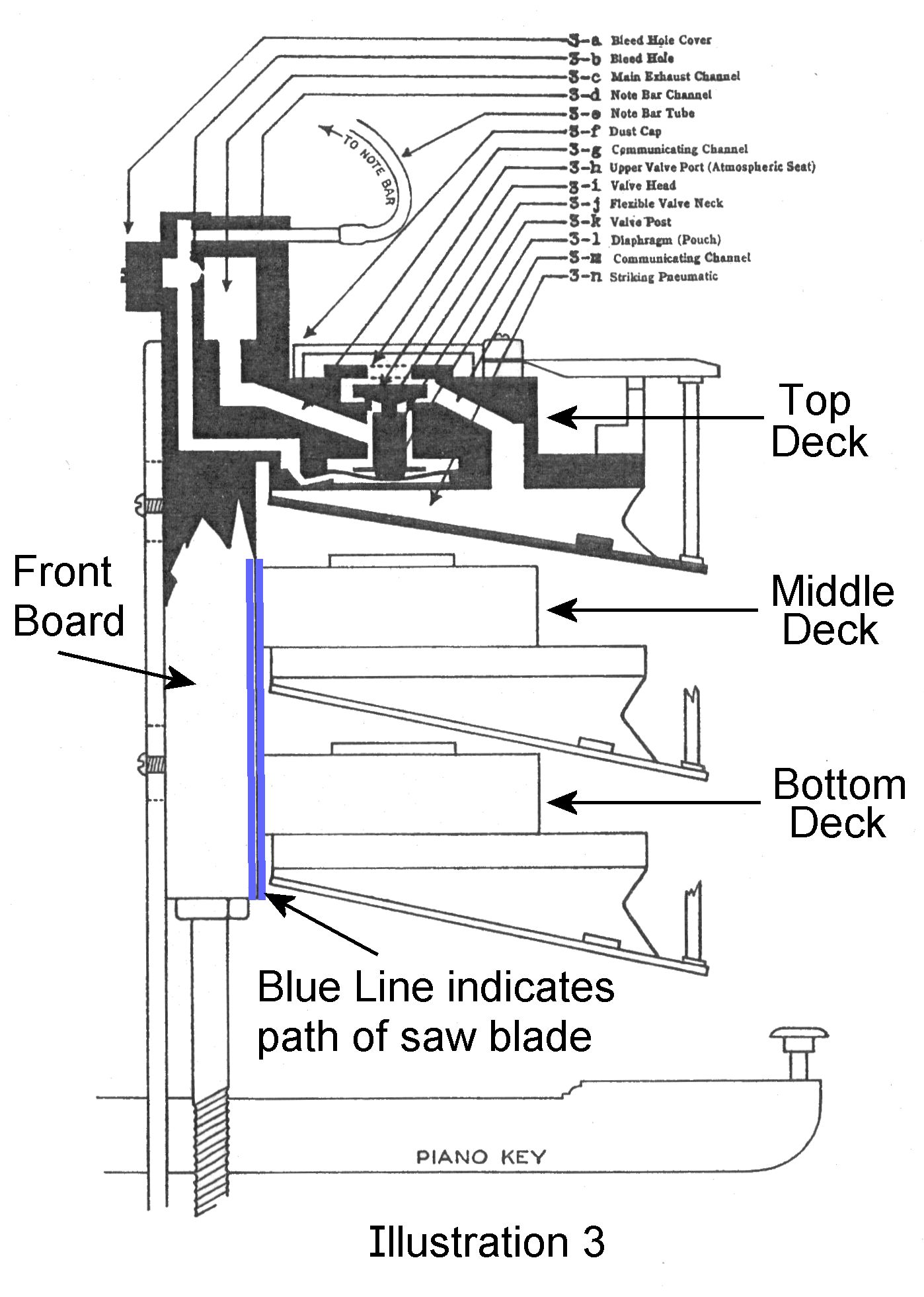 Saw cut placement diagram taken from Illustration 3 in Gulbransen Service Manual. STEP 4 - Remove the stationary half of the pneumatic. The two lower decks should now be hanging by the round supports that go between the decks - remove these now. One hint; before splitting off the pneumatics, it may be wise to take a black felt tip marker and mark where the edges of the pneumatics meet the front edge of the deck. This will aid in realignment when re-gluing. Take one of the decks and lay it on edge on a concrete floor or a very sturdy bench. Lay it on the edge that was just sawed and give one of the pneumatic boards a sharp rap on the end, then drive the thin putty knife between the pneumatic and the deck. The pneumatic should pop off. A little practice here will develop the necessary technique, so begin at the ends of the deck (seldom used notes) and work toward the center. The sharp rap on the end of the pneumatic is to shock the glue which will help it break easier. Sometimes the pneumatic will break away with the sharp rap alone. Remove the pneumatics from all three decks. On the opposite side of the deck are the valve covers. With the putty knife, split all of these away exposing the valve button. (see NOTE below) Pull all the valve buttons off, or all of the fiber discs on the bottom, and lift out all of the valve assemblies. NOTE: Player-Care now offers a Gulbransen Cap Removal Tool which has been proven to help in the removal of the wooden valve cap -click here. STEP 5 - Clean the excess glue off the decks. When splitting away the pneumatic boards from the decks, excess glue will be left between the previous location of the pneumatics. Clean away this excess because it may interfere with re-gluing the pneumatics later. However, do not remove any slivers of wood that were not split away when removing the pneumatics. Leave this glued to the deck as it will aid in realignment later and, of course, if a large piece is removed it may cause an un-tight joint. Also at this time, before putting away the pneumatic boards until a later step, repair any of them damaged in the process of removal from the deck. After they are glued or otherwise repaired, take the hand drill and a bit just a little larger than the small hole at the back of the pneumatic board that goes into the pouch well and drill out any excess glue that may have gotten there as well as drill out the matching hole in the deck. Next, on the sawed joint of the deck, drill this same hole then the hole that goes into the front board of the stack. This will clean away any old dry glue and will help in maintaining an open channel when re-gluing. STEP 6 - Seal all the wood channels with sealer. As mentioned in the introduction, sealing the channels will aid in making a tighter rebuilding job. A sanding sealer on a swab or pipe cleaner run into every channel as far as possible will aid in this. Also seal the drilled channels in the pneumatic and deck. Anywhere there is raw wood, with the exception of the sawed joint where a gasket will be placed, should be sealed. A word of caution, when running a swab into the channels in front of the bleed, be careful not to apply so much sealer that the bleed is plugged. STEP 7.- Add the additional screws necessary for attaching the two decks. There were seven screws (plus the glue) holding the deck to the front board before they were removed to saw the decks off. When putting the deck back later, seven screws will not be enough to insure a tight joint against the gasket. To remedy this add six more screws, one between each existing screw hole. Notice where the existing screws go through the front board in relationship up-and-down to where the deck will seat and also side-to-side where the channel holes are. Drill the holes from the back through the front board being careful not to drill into one of the bleed channels. After these holes have been drilled, screw the deck back in place using the seven original screws. Now use the six additional holes just drilled as pilot holes and drill starter holes for the new screws into the deck. A #8 x l-1/2 inch round head screw is the correct size. Be sure to drill the starter hole deep enough and large enough diameter to avoid splitting when driving later. STEP 8 - Make the gaskets. Remove the screws installed in the last step??? cut a piece of sponge cell neoprene gasket just a little longer than the deck, and with the tube punch cut holes just slightly over-sized for each of the 13 screws. Remember when punching holes in the gaskets that the gaskets should be centered on the decks when installed, so line the holes up and cut them accordingly. To punch the critical holes of the gasket, the paper strip covering the adhesive is not to be removed until step 19. Be sure to cut the gasket so the adhesive part will adhere to the front board, not the deck. Lay the gasket in place on the front board taping in two or three places to hold in place and set the deck on the gasket. Start the four screws that go into the front board through the deck to further insure the gasket will not shift. Check to see that the gasket is centered under the deck and sitting flat. When satisfied that everything is aligned, dip a piece of tracker-bar tubing into some powder so that a little is left in the end of the tube. Blow this into the various holes in the deck thereby marking where holes need to be punched in the gasket material. It will be necessary to do only part of the gasket at a time because when punching holes the powder tends to rub off. However, each time when putting the gasket back to mark more holes, check carefully to be sure it is aligned properly. There are two gaskets to make and they are not interchangeable, so make them accordingly and mark them so there is no confusion later. One other word of advice; select the size of the tube punch hole appropriate to the size of hole in the stack and deck and always check for accurate placement. STEP 9 - Remove and re-glue the brass valve seats. The little brass rings that the leather covered valve buttons rested on are a critical part of the proper player operation. It is these valve seats that seal the stack from outside atmosphere when the note is not playing, consequently the seats must be glued tight otherwise air will leak and the player will not pump easily. Slip a screwdriver blade under the inside bottom and pry up, they should lift out rather easily. Clean out the old excess glue protruding past the floor of the valve well, put a very small amount of plastic glue around the entire outside perimeter of the valve ring and put back in place. The handle of the screwdriver is useful to force this ring back into place. Make sure it is seated fully down as far as it was originally and that it is level. After the glue has dried take some medium steel wool and with the tip of the thumb, polish off the top of each ring. This will serve two functions, to remove any corrosion and also any excess plastic glue that may have gotten on the top surface. Clean them all carefully and check each when done. STEP 10 - Clean and recover the valves. Scrape the leather off the valve buttons making sure all the leather and glue is removed. It may even be necessary to sand lightly, but if so, be sure the button is sanded evenly so it remains flat. Next, clean all the fiber discs that were attached to the bottom of the fluted stem. Very likely the bottom face of the disc has a small dot of some kind glued to it that through the years adhered to the cloth pouch so be sure to scrape away the entire dot. When clean, it may even be well to run these fiber discs over sandpaper very lightly to smooth out. The fluted stems were glued to the leather dot on the top and the fiber disc on the bottom. Scrape and clean them so none of the original glue remains. Take the valve buttons and with proper diameter valve facings, recover the valve. Recover the upper face of the valve with the rough side of the leather facing out and recover the lower face of the valve with the smooth side of the leather facing out. Use the Elmer's glue very sparingly. Any glue that squeezes past the edge and dries will later keep the valve from seating properly, so try to prevent this by using no more glue than enough to attach the leather. Also, when attaching the lower valve facing (smooth side out) no glue should be put in the middle of the button but instead only around the edge. This allows a little give so the valve can seat properly on the brass ring when assembled. When the buttons are finished, take a pointed black marker and put a small dot in the exact middle of the upper (rough side out) valve facing. Next, with a small drop of Elmer's attach the fluted stems to the fiber discs exactly in the middle of the disc. With the revolving tube punch cut small dots of similar diameter and thickness and glue these with Elmer's. Thin leather or thin paperboard will work for the dots. The leather dots that go on top of the fluted stem can probably be cut from the same leather that you will be using for the flap valves. The tolerances here are not extremely close but every effort should be made to find leather as close to the original thickness as possible. STEP 11 - Reinstall the valves. Set a deck up so it is stationary (a couple of paint cans under either end will do) in a horizontal position. Check once more to make sure everything is cleaned off where the valve covers were, check the valve rings once more to see that there is no residual glue on the seats, run a vacuum along the deck to clean any dust out of the various channels and if all looks well, proceed. Lay a valve button in the valve well on the valve seat (brass ring) with the dot up. Center the valve button in the valve well. Take one of the fiber disc-fluted stem assemblies and put a very small drop of Elmer's on the top of the leather dot. Run this assembly with the dot of glue up the channel under the valve button and lift it just far enough so you can see the button begin to rise. Hold it right there very carefully and very still for about 10 or 15 seconds. After that the adhesiveness of the glue will be enough to support the weight of the stem assembly. Complete the remaining 87 valves in the same manner. STEP 12 - Regulate the valve travel and glue the valve covers. One of the more time consuming operations, but critical to the operation of the player for evenness of response of notes, is regulating the valve travel. Lay a new valve cover over the top of the new1y replaced valves and center the hole on the dot. While holding the valve cover down securely check the valve travel with the dial indicator by pushing up from underneath on the fiber disc. There is some divergence of opinion on the proper amount of travel, but whatever number selected, regulate them within 0.002" tolerance. An appropriate amount of travel for proper repetition and a strong pneumatic stroke, yet without excessive travel seems to be around 0.028" travel. If the dial indicator shows too much travel, glue another top valve facing (rough side out) to the top of the button. Don't forget to put another black dot in the middle. If the dial indicator shows too little travel, space the cover up using very small pieces of paper, such as balance rail punchings cut into three or four pieces. When the correct amount of travel is obtained, run a bead of Elmer's around the cover, assuming it again has been very carefully centered, so the glue contacts the edge of the cover and the stack around the entire perimeter of the cover. This will assure a tight joint. After the glue is dry check the travel of the valve again. Many times the glue will tend to lift the cover just a little while it dries. If so. the travel will be too much and the cover will have to be re-set. A little experimentation will produce the desired results of learning how far off the drying glue shifts the cover. Compensate on the remainder of the covers when gluing. STEP 13 - Regulate the tracker tubing nipples in the stack. The small brass nipples that were removed in step 1 may now be replaced. Run a little plastic glue around the nipple and put it back in the hole. At the same time, the large brass elbow supplying the suction from the bellows can be replaced, also with plastic glue. This done, lay the decks and front board with one deck attached aside. Find a safe place where the fiber discs will not get knocked off as they are vulnerable. STEP 14 - Glue in the new pouches. Clean off all the pneumatic stationary boards. Not only the old cloth around the outside but also the old pouch. Once entirely clean, using your favorite pouch material put in the new pouch. If using leather which would probably be easiest if this is the rebuilder's first player, run a bead of Elmer's around the inside of the pouch well on the top of the lip. Use enough glue so the pouch will be glued tightly but not so much that the excess glue squeezes out onto the movable area of the pouch. Lay the pouch across the top of the well and push down into place using a pouch setter. If no pouch setter is available the fingers can be used but it takes longer, the pouches will not be as consistent, and it will be necessary to press the edges of the pouch into the glue all around the edge to assure a tight pouch. After the pouches are all installed, assuming leather was used, seal the pouch by brushing on a thin coat of Carter's rubber cement mixed with naptha one-to-one. After the sealant has dried put talc or similar powder on the pouches to spoil any stickiness remaining thus preventing the fiber discs with dots from sticking. If polyurethane pouches are used no sealing is necessary. STEP 15 - Recover the pneumatics. The stationary part of the pneumatic was cleaned off in step 14, now clean the old pneumatic cloth off the movable portion of the pneumatic. Match the pneumatic boards, movable to stationary, and when paired off, put a rubber band around each pair. Cut cloth hinges from the pneumatic cloth to be used for recovering the pneumatics and glue the hinge in place. When the hinges have dried thoroughly, check to see that they are all tight but not binding. Cover the pneumatic, working carefully and consistently. Take care that excessive use of glue does not cause binding in the hinge end. The jig from Player Piano Company is helpful in covering Gulbransen pneumatics because many have the finger and the PPC jig comes with instructions on how to accommodate this finger. When all the pneumatics have been covered and trimmed, check to be sure they close easily and if they don't, rework them. One word about trimming off the excess cloth. Be certain the cloth trimmed off the stationary side of the pneumatic is trimmed all the way down flush with the top side of the pneumatic otherwise it could interfere with getting a tight glue joint in step 16. All Gulbransen pneumatics have a 1-1/4 inch span - measured from the outside to the outside across the two boards on the end of the pneumatic. STEP 16 - Glue the pneumatics to the deck. This step is probably the most difficult of the entire rebuilding operation in the Gulbransen. However, the difficulty lies in attention to detail. Once the basic idea is mastered, the rest is knowing what to look for and listen for. First, much of the success lies in having the hot glue the proper consistency. There must be enough body to the glue so the pneumatic seals properly but watery enough so that it does not set too quickly. Get a piece of tracker-bar tubing with a brass nipple in one end that will fit tightly in the hole in the back of the deck that is the channel leading to the pouch. Force this nipple into this hole and place the other end of this tube in the mouth. Spread an ample amount of glue on the face of the pneumatic and quickly put the pneumatic in place. Check the alignment very carefully. Look for the line across the stationary part of the pneumatic where it originally met the deck, check the old glue lines between the pneumatics, and check the black marks made in step four. Immediately pull the pneumatic away from the deck and blow through the tube in the mouth. Any excess glue in the pouch channel in the deck will be blown out of the hole. Catch this with a swab, then check the matching hole in the pneumatic and also fish out any excess glue. Notice the thin edges of the pneumatic face on either side of the pouch, it may be wise to put just a bit more glue here to insure a tight seal and then put the pneumatic back in place and clamp. Inspect to see if glue is squeezing out all around the pneumatic, if so you probably have a tight joint. Now alternately blow and suck on the tube and you should hear the pouch and valve working without any leaks around the joint. Usually there should be no concern about plugging the large hole going to the pneumatic itself from the valve as the hole is large enough to avoid becoming clogged and of course a little glue squeezed into the pouch area will be of no concern unless there is an excessive amount to foul the movable portion of the pouch or the fiber disc. Due to evaporation, the consistency of the glue will have to be checked constantly. Have all necessary items handy such as swabs, glue, clamps, blow tube, etc., because hot glue sets very rapidly. When beginning to brush the glue, everything should follow in one continuous motion until the pneumatic is clamped in place not more than 20 to 30 seconds later. Gluing the pneumatics to the deck that was left attached to the front board is just a little different. The blow tube is attached to the appropriate nipple at the top of the stack and a piece of masking tape will need to be placed over the holes to the bleed channel on the top and the front of the front board. Otherwise everything is the same, except when blowing and sucking on the tube to check the channel after clamping, remember the bleed hole is in the line. Because of this the pouch will offer less resistance which may be interpreted as a leak unless expecting it. STEP 17 - Test the valves. and pneumatics. See the testing jig sketch (below). Insert the rubber tube 'Y' connector end in the large hole making sure of a tight fit and the brass tube 'Y' connector end in the pouch channel or small hole on the back of the deck. Now apply vacuum to the pneumatic with your mouth and the pneumatic should close as long as the short tube is open. Putting your finger over the end of the short tube is the same as closing the hole at the tracker-bar when a roll is playing, finger off is the same as playing a note. Check for leaks, proper repetition, and proper seating of the valve. Test all of the pneumatics and valves on the two sawed decks then check the deck still glued to the front board. Because access is not possible to the vacuum supply hole for each valve and pneumatic individually on the deck still glued on, a different procedure is necessary. First connect the blow tube to the right nipple at the top of the stack, as when gluing the pneumatics back, then blow and suck, watch the valve travel, and if it looks OK, place your thumb over the hole in the valve cover, or otherwise cover it so it is airtight, and force the pneumatic closed. If it closes very slowly it is functioning as should be. That is, the lower valve seat sealing and because there is no other escape for the air, you do not have any leaks. If it closes easily check for leaks. While forcing the pneumatic shut try blowing into the suck tube in your mouth. The pressure should release immediately and if it does and then reseals when you don't blow, the valve is probably functioning.
 STEP 18 - Cleaning and recovering bleed channels. While working, it's probable that small pieces of glue, pneumatic cloth, rubber or other extraneous material may have gotten into some of the stack channels. Take a vacuum with a strong suction and go over each hole carefully - not only the holes on the back face of the front board where the decks have been sawed away, but also the bleed channels on the top and front of the deck. When the stack has been thoroughly cleaned, cut a strip of pneumatic cloth suitable width for covering the bleed channel holes on the top and glue the cloth in place. With a small piece of wire clean each bleed hole visible through the front ports, vacuum again, then screw the covers in place. Check to make sure the cover facing gaskets are good. If not, replace with suitable leather so they will seal. STEP 19 - Screw the two decks back in place. When everything is checked, working, and cleaned, get out the gaskets made in step 8. Check once more to be sure all holes are aligned exactly. Pull off the paper covering and press the adhesive into place on the front board. Put the middle deck into place and start a couple of screws through the front board for alignment, then put the small support posts, removed in step 4, back in place and tighten. Do the same with the bottom and middle decks, starting a couple of screws for alignment then putting in the support posts. Now add the remainder of the screws in each deck. Tighten them all evenly and sufficiently to get some compression of the gasket material and to insure a tight seal but not so much that there is a danger of stripping or splitting the wood. STEP 20 - Test the entire stack. Attach a hose and vacuum to the main supply elbow coming from the stack. Cover all the small brass tracker tube nipples with a piece of tape and turn on the vacuum. With all the small nipples covered none of the pneumatics should close. When the tape is pulled off the nipple the pneumatic should slap shut sharply; putting your finger over the nipple should cause it to reopen. Check the note individually several times and each one rapidly to check for repetition. If each note works as it should, the hardest part is now over. STEP 21 - Reinstall the incidental stack parts. Put back the various parts that were removed in step 2, such as the dust cover over the top row of valves, the boards topped with felt that go below and in between the rows of pneumatics to limit their throw, and the fingers (if your piano is equipped with these) that contact the piano action. lt may be necessary to make new hinges for the fingers, new felt dots on the end of the push rods, etc., but a little ingenuity here will provide all that is necessary. The lower half of the stack is finished. STEP 22 - Clean, polish, and check. the upper part of the stack. Before reattaching the two halves of the stack, remove the transmission and clean it with lacquer thinner, remove the tracker-bar so that it can be cleaned of the remainder of tubing on the nipples then polished, and clean and polish any other metal parts that are discolored or corroded, especially the parts that will be exposed to view in the spool-box. While these metal parts are out, consider painting the spoolbox if the paint is chipped or scratched. Under the deck that the motor and spool-box sit on is a small valve that opens when the wood button, that comes through the floor of the spoolbox near the right side, is pushed or when the transmission is put in rewind - remove this valve. The spring that holds the movable part of the valve doum pulls straight out. When out, replace the leather facing on this small board and also steel wool the brass lip that this leather seats against. Reassemble, remove the brass nipple for the tube, reglue and when the glue has dried put a suck tube on the nipple and check for tightness. When assured it is tight, put it back in place then connect the upper and lower halves of the stack. First the brackets at either end (might as well screw on the front support brackets at the same time) with the thumb screws, then put the hinges in place and run the screws back in. STEP 23 - Rebuild the pneumatic motor. Before taking the motor apart take a little time to understand how it works. Sketch VII in the service manual should be of help. Number the three pneumatic pairs, pull off the cloth on the back and remove the two screws. Drive the thin putty knife between the body of the motor and the pneumatics so they split off. If you haven't already, remove the arms that attach to the movable board of the pneumatics. Remove the left supporting block, then remove the right rotating (the one on the outside) metal valve - be careful not to lose the small spring, washer and clamp with the set screw. Pull these off the shaft and pull the shaft out of the hole. Start the parts just removed back onto the shaft and tighten the set screw so they don't drop off. Now where the motor frame and block meet at the junction there is very probably a leak. Take this joint apart, clean and reglue using hot glue, making sure everything seals. The wooden seat that the rotating metal valve rides on very likely is starting to come unglued somewhere around its perimeter. Split it off carefully and reglue. Be certain it is glued back on exactly in the same place it came off. Where the rotating shaft goes through this rotating valve assembly there is a felt bearing; check this and replace if necessary. When the channels are apart or even after they are together it would improve the operating efficiency of the motor to seal the wood in the channels. When covering the three paired pneumatics with new cloth, one piece of cloth can be used if worked carefully, but it may be easier to use two. First cover one side with the movable board as far one way as it will go, then crease the cloth tightly and move the board the other way to cover the opposite side. Cover each pneumatic pair exactly the same, always checking to make sure the middle board does not become glue bound and works easily. Glue back in place and recover the holes with a scrap piece of bellows cloth. Rub graphite into the wooden valve seats for the rotating valves by dampening them first with alcohol then re-install the shaft and left block. STEP 24 - Rebuild the rinky-tink pneumatic and valve. (if present). The Gulbransen's rinky-tink is usually a pneumatic that is screwed to the back of the spool-box. This one single unit is just like the 88 just rebuilt down in the stack. A little examination will reveal how the pneumatic comes off, how to split the top off to get at the valve and that the reassembly procedure is the same as the pneumatics and valves in the rest of the piano. STEP 25 - Retube the stack. If you removed the tracker-bar in step 22, it should be put back in place. Run a tube from the large opening at the left end of the tracker-bar to the sustaining on-off switch around on the left end of the spool-box, then run a tube out to the left end of the stack, cut the tube and install a brass nipple. The nipple is put in the line so that in the future if the stack needs to be replaced it is convenient to slip the tube off the nipple. Next, do the same from the small rewind valve mentioned in step 22. Now run the tubes from the tracker-bar to the nipples on the stack. It may be easier to tube the bottom row of nipples on the tracker-bar to every other nipple on the stack first and then do the top row. If the tube is moistened with saliva before slipping it on the tracker nipple it will go on easier. Only leave enough slack so the top of the stack can be tipped forword in future years to tune the piano without kinking the tubes. Too much slack in the tubes will tend to sag down and interfere with piano action operation by not letting the back checks return fully. If your piano has the rinky-tink pneumatic, replace the back of the spool-box thereby putting the rinky-tink back in place and run the supply tube to the stack, usually a nipple-elbow directly below. Also run the tube that controls the pouch out to the left end again with a nipple for possible disconnect. Before step 26, place a test roll in the spool-box, connect vacuum to the stack and turn the test roll by hand. Check not only to see that each pneumatic is working but to see that they are working sequentially. It is easy to get a tube misplaced when tubing. To keep the tubes out of the piano action take black plastic tape and in several places tape the tubes in bundles. (Refering here to the tubes that run toward the ends of the stack and not the tubes directly behind the spool-box). STEP 26 - Install the stack - see service manual illustration IV. When putting the stack back into the piano the one thing that is most often overlooked and which will prevent proper operation more than any other is regulating out all the lost motion between the striker fingers of the stack and the contact points of the piano action. When at rest the striker finger should be just ready to move the piano action but not touching it. If the piano action is held up even a little bit the keyboard will tend to look uneven and will not play properly because it will not have a full stroke when playing a note. Or if the player has to move more than a 64th of an inch before the action moves it will be noisy and ineffecient. Spare no time and effort regulating the lost motion. The major adjustment can be made by turning the large capstan lag screws that the stack rests on, but be sure all the screws in the slotted brackets are loose first. When these are regulated to approximately the correct height, retighten the screws in the slotted brackets, tip the spool-box toward you and with a crimped wire tool adjust each contact regulating button. Tighten it until the hammer begins to lift and then back it off a half turn (a rough rule of thumb). STEP 27 - Rebuild the bellows and other units in the piano's lower half. See service manual Sections I, II, IX, and X. There are no special skills involved here not already developed. Recover all the bellows, replace the flap valve leather with new and while the bellows assembly is all apart check the leather facings on the valves that that shut off the stack during rewind and bypass the governor to the motor. As with the rinky-tink. Split the valve assemblies and recover the pneumatics for the rewind pneumatic that sits on the front of the left reservoir bellows and also the sustaining pneumatic. If there is a pushbutton valve in the keyslip to operate the rinky-tink, redo this much as the rewind valve under the spool-hox. Before reassembling the bellows, check for any cracks in channels and if found cover with pneumatic cloth and glue. Don't forget to measure the span of the governor before recovering as the exact span is important to proper operation. When recovering the pumping bellows, there were probably cardboard rib stiffeners inside. For best operation these should be duplicated and replaced. However as a short-cut, rib stiffeners can be glued to the outside of the bellows cloth once the bellows are recovered. (not recommended) STEP 28 ... Test and reinstall the bellows??? When all are back in the piano and before hooking up the hoses and tubes, put tape over the various openings in the bellows and exhaust all the air with the pedals. If you have done a careful job the big reservoir bellows will probably not completely open for at least 30-40 seconds. If no leaks are detected hook up the hoses and also the three tubes coming down the left side. It will probably be necessary to do a little adjusting on the tracking regulator, if your piano has one, and also adjust the tempo according to the service manual. Otherwise, if each step has been done carefully and you checked yourself as you worked, everything should be ready to enjoy.
It is wise to pump the tracker bar frequently at first because of foreign material getting in during the rebuilding process and regularly thereafter to keep the bleeds open and working. Also it is useful to keep the test roll handy and run it through now and then just to keep tabs on how well the piano is working. Have the piano tuned and serviced regularly and keep adequate amounts of humidity in the house in the winter if forced air heating is used. Don't set the piano in front of a heat register, a window, or even an outside wall unless insulated well. And play the piano frequently. As a matter of fact, it is not unusual for a player that has been completely rebuilt as done here to play easier as time goes by because it takes a while for the new valve leather to seat on the brass rings and for the pneumatics to become more flexible. Because the Gulbransen tends to stand up well to the effects of time and because a well rebuilt Gulbransen player works so easily, they are a very good player to own. Happy pumping! |

|
Since "Player-Care" is an internet business, I prefer that we correspond via E-Mail (click here to fill out the 'Request Form'). However, if I'm not in the middle of some other activity, you can reach me at 732-840-8787. But please understand that during the hours from 8AM-5PM EST (Mon-Sat), I'm generally quite busy. So, I probably won't answer the phone. If you get the answering machine, please leave a detailed message stating the reason for your call. Also, repeat your name and phone number clearly and distinctly. By necessity, I prioritize everything in my life. And, if you call and just leave your name and number, and ask me to call you back, it might be a day or two before I return your call. Why? Because I don't know why you want me to call and I might not be prepared to assist you in an effective and efficient manner. If you leave me an E-Mail address (which I prefer), spell it out phonetically. The more you do to help me, the more I can help you in return. Don't rush. You have four minutes to record your message. |
|
407 19th Ave, Brick, NJ, 08724 Phone Number 732-840-8787 (Voicemail Only, No Texts) |
