
|

|

|
|
|
|
|
| Home | Manuals | Supplies | Search | Consult | Contact | Testing | Service |
|
UNITED STATES PATENT OFFICE. CHARLES FREBORG. OF DE KALB, ILLINOIS. ASSIGNOR TO GULBRANSEN, DICKINSON COMPANY. OP CHICAGO, ILLINOIS, A CORPORATION OF ILLINOIS. FLUID-MOTOR. No. 882,672. Specification of Letters Patent. Patented March 24, 1908. Application filed May 7. 1906. Serial No. 315,465.
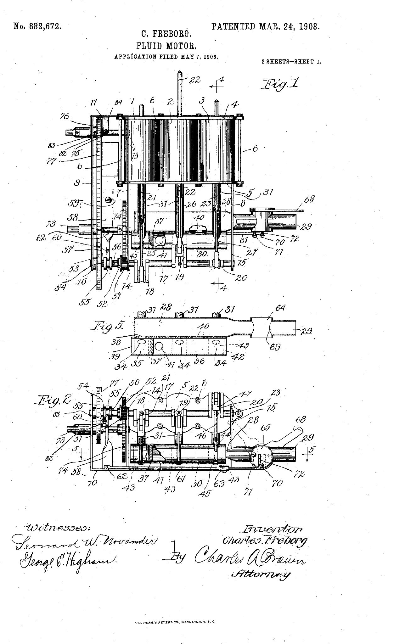
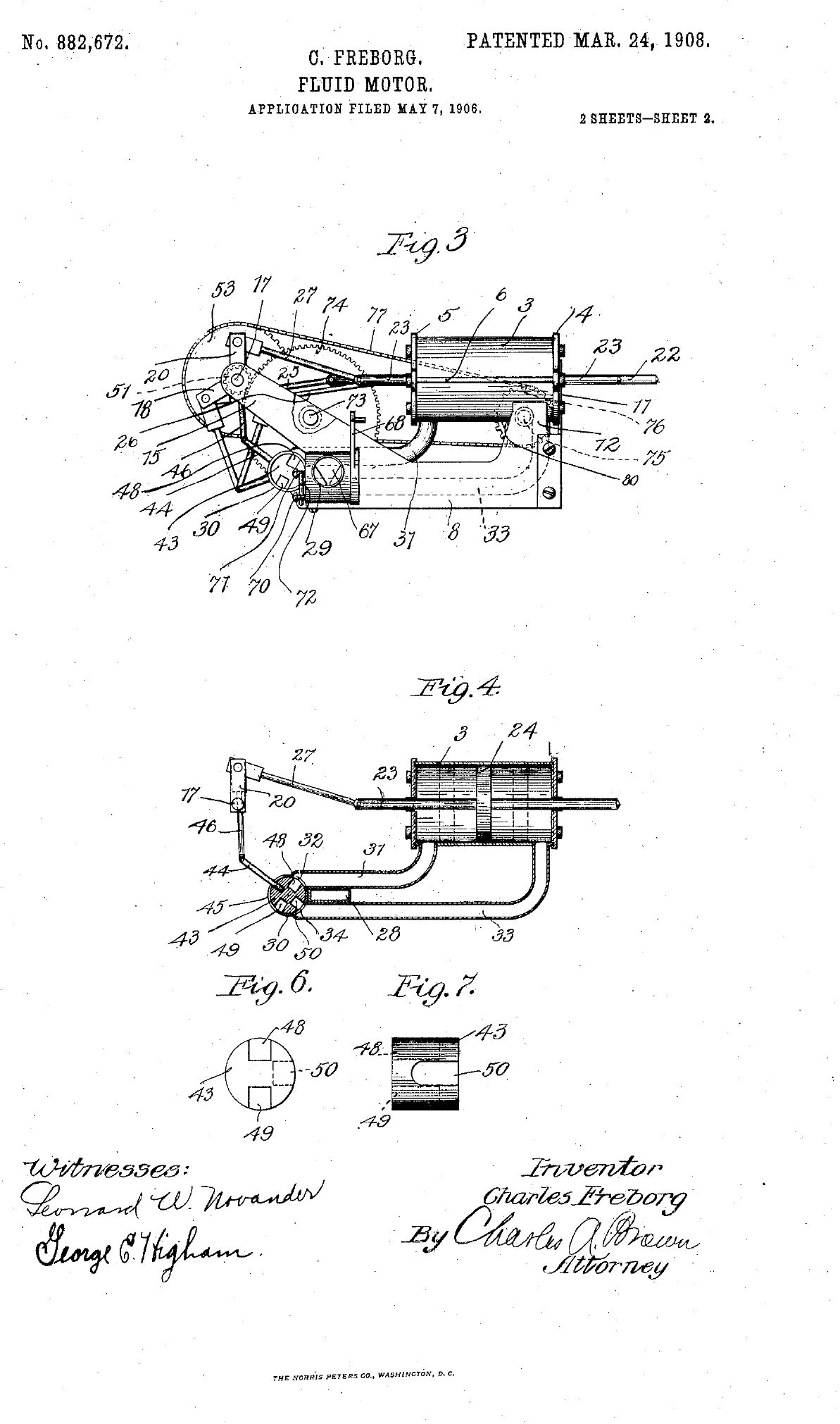
To all whom it may concern: Be it known that I, CHARLES FREBORG, a citizen of the United States, residing at De Kalb, in the county of Dekalb and State of Illinois, have invented a certain new and useful Improvement in Fluid - Motors, of which, the following is a full, clear, concise, and exact description reference being had to the accompanying drawings, forming a part of this specification. My invention relates to fluid motors, particularly to air motors for use in automatically played pianos, and my invention contemplates improved features of construction which will be best understood with reference to the accompanying drawings, in which Figure 1 is a plan view of the motor. Fig. 2 is a front end elevation thereof. Fig. 3 is a side elevation thereof. Fig. 4 is a sectional view through a cylinder and the valve mechanism taken on line 4-4 of Fig. 1. Fig. 5 is a sectional view of the air supply and valve chambers taken on line 5-5 of Fig. 2. Fig. 6 is an enlarged end view of a valve which I employ. Fig. 7 is a side elevation of the valve. The motor is constructed entirely of metal and is provided with three cylinders 1, 2 and 3, whose rear walls are formed by the common plate 4, and whose front walls are formed by the common plate 5, said plates 4 and 5 being connected together by bolts 6-6 parallel to the cylinders. The motor supporting frame comprises the side walls 7, 8 and 9, the base wall 10 and the rear wall 11. The cylinder frame is secured between the vertical extensions 12 and 13 from the side walls 7 and 8, these extensions being preferably soldered or otherwise secured to the end cylinders. Arms 14, 15 and 16 extend forwardly and upwardly from the walls 7, 8 and 9, respectively, and in their ends is journaled the crank shaft 17 having the cranks 18, 19 and 20 displaced 120 degrees from each other and disposed in alignment with the cylinders 1, 2 and 3 respectively. The piston rods 21, 22 and 23 of the cylinders each terminate in a piston head 24 and connecting rods 25, 26 and 27 respectively connect the piston rods with the respective cranks on the crank shaft. Extending between the front of the side walls 7 and 8 is the air chamber 28 adapted for connection through a pipe 29 with a source of compressed air or suction. Immediately in front of the air chamber is the valve chest or tube 30, and as best shown in Fig. 4, each cylinder has two connections with said valve chest. An upper pipe 31 connects the front part of each cylinder with an upper opening 32 into the valve chest, while a lower pipe 33 connects the rear end of each cylinder with the lower opening 34 into the valve chest. The valve chest is divided into two compartments 35 and 36 by the partition 37, the pipes from cylinder 1 leading to compartment 35, and this compartment is connected through opening 38 with the air chamber 28, and with atmosphere through the open end 39 of the valve pipe. The pipes of the cylinders 2 and 3 connect with the compartment 36, this compartment being connected through opening 40 with the air chamber and to atmosphere through the opening 41 and through the open end 42 of the valve chest, the opening 41 being between the partition 37 and the inlet openings from the pipes of cylinder 2, and the opening 40 being between the pipes of cylinders 2 and 3. Before the set of openings of the pipes from each cylinder is disposed a valve 43, the valves being cylindrical and fitting within the cylindrical bore of the valve chest. A valve stem 44 extends from each valve through a slot 45 in the valve chest and through a connecting rod 46 and crank head 47 pivots to the corresponding crank on the crank shaft, and thus upon reciprocation of the pistons and rotation of the crank shaft the valves will be oscillated. The detail construction of the valves is shown in. Figs. 6 and 7, each valve having diametrically opposite exhaust grooves or channels 48 and 49 and an inlet groove or channel 50 at 90 degrees with the outlet channels, the centers of the openings 32 and 34 being also displaced 90 degrees. The valve for the cylinder 1 is arranged in the compartment 35 with its exhaust channels 48 and 49 leading toward the outlet 39 and with its inlet channel 50 on the side adjacent to the openings from the cylinder pipes. The valve for cylinder 2 is within compartment 36 with its exhaust channels leading toward the atmosphere outlet 41 and with its inlet channel adjacent to the outlets of the pipes from cylinder 2. The valve of cylinder 3 is also in compartment 36 with its exhaust channels leading toward the open end 42 of the valve chest and with its inlet channel adjacent to the openings of the pipes from cylinder 3. In Fig. 4, the disposition of each valve with respect to the pipes from the corresponding cylinder is plainly shown, the inlet channel upon reciprocation of the valve being earned to and fro between the openings 32 and 34 to alternately connect the front and the rear of the cylinder with the air chamber 28, and when one end of the cylinder is connected with the air chamber the other end is in communication with atmosphere through one of the exhaust channels. When the inlet channel communicates with the rear end of the cylinder the exhaust channel 48 communicates with the front part of the cylinder, and when the inlet channel communicates with the opening 32 and the front part of the cylinder, the rear end of the cylinder communicates with atmosphere through pipe 33 and exhaust channel 49. The operation of all the valves is similar, but there is a displacement of 120 degrees between them. This arrangement of the valves and the feeding of energy to both the front and rear of the pistons gives the same effect as six cylinders in which energy is supplied to only one side of the cylinder. The motor, therefore, with the same number of parts is given double efficiency and its operation is very regular and steady. This motor may be driven by air under pressure or vacuum, or may be driven also by liquid, such as water, and the motor may be utilized for driving any mechanism. I have, however, shown it utilized for driving the music roll and the take up roll for a mechanically operated instrument, such as a piano or organ, and I also provide controlling and switching mechanism. Loosely mounted on the crank shaft between the arms 14 and 16 and adjacent the arm 14 is a pinion 51 having a clutch tooth 52 extending from its side to the left. Loosely mounted on the crank shaft with and adjacent the arm 16 is a sprocket gear 53 having a clutch pin 54 extending to the right. Keyed to the crank shaft between the pinion and gear to be longitudinally movable thereon is the clutch collar 55 having the clutch pins 56 and 57 for engagement with the clutch pins 52 and 54 respectively. A clutch lever 58 pivoted to the frame 59 has the forked end 60 for engaging the clutch collar, and a rod 61 pivoted to the clutch lever at 62 extends to the right, passing through the guideway 63 secured to the frame, as best shown in Fig. 2. Interposed in the pipe 29 is a cylindrical valve chamber or seat 64 in which engages the valve 65 having a V-shaped notch 67 cut in its periphery, as best shown in Fig. 3. An actuating arm 68 extends from the valve, and as the arm is oscillated the valve notch will move by the opening 69 from the valve chamber to control the passage of energizing fluid to the chamber 28. When the arm is in its extreme position to the right, the valve will be wide open and when the arm is in its extreme position to the left, as shown in dotted lines, the valve will be entirely closed. Extending from the front face of the valve are the posts 70 and 71 between which the upturned end 72 of the rod 61 extends. These posts are near the periphery of the valve, and their angular displacement is such that the valve may be moved through an arc independently of the rod 61. When the rod, however, reaches its extreme right position, post 70 will come into engagement with and cause movement to the left of the rod 61. The valve lever may then be rotated toward the left a considerable distance without causing movement of the rod 61, but when the lever reaches its extreme left position, post 71 comes into engagement with the rod 61 and returns this rod to its position at the right. When, the rod is moved toward the left, it causes clutch collar 55 to engage with gear 53 to connect said gear in driving relation with the crank shaft, and when the rod 61 is moved to the right, the clutch collar 53 will connect the pinion 51 in driving relation with the crank shaft, and, therefore, the crank shaft can be made to drive either the gear 53 or pinion 51 to drive either the shaft 75 or the shaft 73. After the valve lever has been moved to an extreme position to carry the rod in one direction and to establish certain gearing relations, the valve may then be operated independently through a wide range to control the air flow to the motor cylinders, it being, only at the extreme end of the throw of the valve lever that the clutch rod 61 is moved by the posts 70 or 71. A shaft 73 journaled in the arms 14 and 16 supports a gear 74 which meshes with the pinion 51. A shaft 75 bears in the side walls 7 and 9 to the rear of the shaft 73 and supports a sprocket wheel 76 connected with the sprocket wheel 53 by the chain 77. The shaft 75 may engage with the roller on which the music to be wound is played, this roller not being shown. The shaft 73 may engage with a roller (not shown) for taking up the music from the roller connected with the shaft 75 after its passage over the tracker board in the well known manner. When the clutch collar which is keyed to the crank shaft is slid to connect with the pinion 51, the gear 74 and shaft 73 will be driven at a suitable speed, the sprocket gear 53 being idle during this time. After the music has been played the clutch collar engages with the sprocket gear 53 and the adjustment may be such that the roller connected with the shaft 75 is driven at a suitably increased speed to rewind the music from the roller connected to shaft 73. During this rewinding period the arm 68 is at the extreme right and the valve 65 wide open. Preparatory to driving the roller connected with shaft 73, the valve is completely closed, and upon movement toward the right, the valve is opened and the motor started, its speed being then controlled and varied, as desired, by the manipulation of the lever 68 to adjust the V-shaped slot of the valve. The motor being constructed entirely of metal is free from distortion or warping, which would take place were the motor constructed of wood or other less permanent material. The movable parts can also be much better lubricated and the friction reduced to a minimum, and-in a motor of this kind there is also less wasted energy resulting from leakage of the fluid. Changes may readily be made in the exact construction and disposition of the parts without departing from the spirit of my invention, and I do not, therefore, wish to be limited to the construction and arrangement shown and described. What I claim as new and desire to secure by Letters Patent is: 1. In a fluid motor, the combination with a plurality of cylinders 1, 2 and 3, each having a piston therein, of a crank shaft having angularly displaced crank arms connected with said piston, a common valve chest in the form of a cylindrical tube, a cylindrical valve in said valve chest for each cylinder, each valve being connected with the corresponding crank arm to be oscillated upon rotation of the crank shaft, a supply chamber adjacent said valve chest and communicating therewith, a connection from the front end of each cylinder to a port opening in said valve chest, a connection from the rear end of each cylinder to another port opening in the valve chest, exhaust openings from said valve chest, a supply channel 50 for each valve adapted upon oscillation of the valve to alternately connect with the port openings whereby fluid is alternately fed to front and rear ends of the cylinders, and exhaust channels 48 and 49 for each valve adapted to connect one end of the cylinder with the atmosphere, while the other end is in connection with the supply source. 2. In a fluid motor, the combination with a cylinder having a piston therein, of a crank shaft connected with the piston to be rotated, a driving pinion on said crank shaft, a driving gear on said crank shaft, a valve chest, a supply chamber connected with a fluid supply source through a supply pipe, a valve within the valve chest controlled by the movements of the piston to control the supply of energy from said supply chamber to the cylinder, a valve in the supply pipe, clutch mechanism associated with the driving pinion and gear, lever mechanism extending from the clutch mechanism and in engagement with the valve in the supply pipe, said valve when moved in one direction causing the supply pipe to be open and causing movement of the lever mechanism to engage the clutch mechanism with the driving gear, said valve when moved in the opposite direction causing closure of the passageway and causing actuation of the lever mechanism to engage the clutch mechanism with the driving pinion. 3. In-a fluid motor, the combination with a cylinder having a piston adapted for reciprocation therein, of a crank shaft connected with the piston, driving gears on said shaft, a valve chest, a fluid supply chamber adjacent said valve chest and in communication therewith, a supply pipe in said supply chamber, a supply valve in said supply pipe, a controlling valve in said valve chest controlled by the reciprocation of the piston to control the flow of energy to the cylinder from the supply chamber, a clutch collar keyed to the shaft between the driving gears, lever mechanism extending from the clutch mechanism to the main valve, extensions 70 and 71 from the main valve, and extensions 72 from the lever mechanism adapted for engagement with the extensions 70 and 71 when the valve approaches its extreme position, said main valve when moved toward one extreme position causing opening of the passageway and actuation of the lever mechanism to connect the clutch with one driving gear, actuation of the valve toward its other extreme position causing closure of the passageway and actuation of the lever mechanism to move the clutch mechanism into engagement with the other gear. 4. In a fluid motor, the combination of a cylinder having a piston for reciprocating therein, a crank shaft connected with the piston to be rotated upon reciprocation of the piston, a driving gear, and a driving pinion loosely mounted on said crank shaft, a clutch collar on said crank shaft between the gear and pinion, said collar being longitudinally movable on said crank shaft but keyed thereto to rotate therewith, a valve chest, a fluid supply chamber connected with the valve chest, a valve in the chest for controlling the fluid supply to the cylinder, a main, valve controlling the flow of fluid to the fluid chamber, and connecting means between the clutch collar and the main valve mechanism, said main valve mechanism through a certain range of movement being independent of the connecting mechanism but adapted for actuating said connecting mechanism throughout another range or movement to cause movement of the clutch collar to connect the crank shaft with either the gear or pinion thereon. 5. In a fluid motor, the combination, of a cylinder having a piston for reciprocating therein, a crank shaft connected will the piston, a fluid supply reservoir, a valve for controlling the connection of the cylinder with the fluid reservoir, a main valve controlling the supply of fluid to the reservoir, clutch mechanism on the crank shaft, gearing mechanism adapted for connection with said clutch mechanism, and connecting mechanism between the clutch mechanism and the main valve adapted to be actuated during certain ranges of movement of the main valve mechanism to operate the clutch mechanism, said main valve mechanism during another range of movement being independent of the connecting mechanism whereby the flow of fluid to the fluid reservoir may be controlled. 6. In a fluid motor, the combination of a cylinder having a piston for reciprocation therein, a crank shaft connected with the piston, a fluid reservoir, valve mechanism for controlling the connection of the fluid reservoir with the cylinder, an oscillatory main valve for controlling the supply of fluid to the reservoir, clutch mechanism driven by the crank shaft, gearing mechanism adapted for connection with the clutch mechanism, and connecting mechanism between the clutch mechanism and the main valve, said connecting mechanism being operated by the main valve only at the ends of its oscillation to connect the clutch mechanism with the gearing mechanism, said main valve during an intermediate part of its oscillation being independent of the connecting mechanism. 7. In a fluid motor, the combination of a supporting frame of sheet metal, a plurality of cylinders mounted side by side in a row on said frame, a piston and a piston rod for each cylinder, a valve chamber in the form of a tube mounted on the frame in front of the cylinders, a pipe leading from the front of each cylinder to the top of the tubular chamber, a pipe leading from the rear of each cylinder to the bottom of the tubular chamber, a flat air reservoir disposed adjacent the tubular chamber and between the upper and lower pipes, a rotary valve associated with each set of pipes and with the reservoir, and a connecting rod connecting each valve with the crankshaft to be oscillated upon rotation of the crank shaft.
In witness whereof, I hereunto subscribe my name this 16th day of April A. D., 1906.
Witnesses: |
| Player Piano Reference Materials - Click Here |

![]() ..To
The Top of this Page . . . . . . . . . . .
..To
The Top of this Page . . . . . . . . . . . ![]() ..To The HOME Page
..To The HOME Page
|
Since "Player-Care" is an internet business, I prefer that we correspond via E-Mail (click here to fill out the 'Request Form'). However, if I'm not in the middle of some other activity, you can reach me at 732-840-8787. But please understand that during the hours from 8AM-5PM EST (Mon-Sat), I'm generally quite busy. So, I probably won't answer the phone. If you get the answering machine, please leave a detailed message stating the reason for your call. Also, repeat your name and phone number clearly and distinctly. By necessity, I prioritize everything in my life. And, if you call and just leave your name and number, and ask me to call you back, it might be a day or two before I return your call. Why? Because I don't know why you want me to call and I might not be prepared to assist you in an effective and efficient manner. If you leave me an E-Mail address (which I prefer), spell it out phonetically. The more you do to help me, the more I can help you in return. Don't rush. You have four minutes to record your message. |
|
407 19th Ave, Brick, NJ, 08724 Phone Number 732-840-8787 (Voicemail Only, No Texts) |
