|

|

|
|
|
|
|
| Home | Manuals | Supplies | Search | Consult | Contact | Testing | Service |
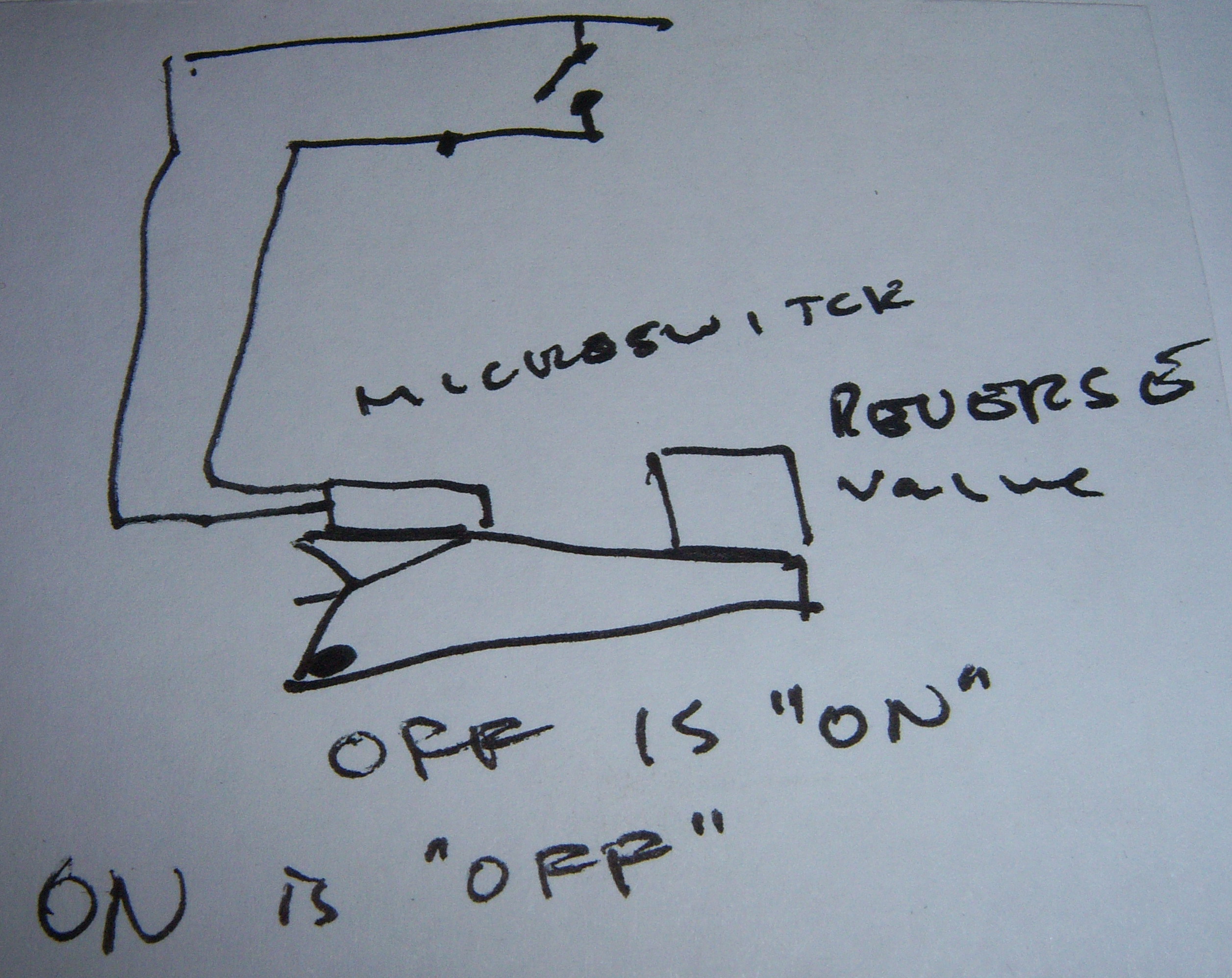
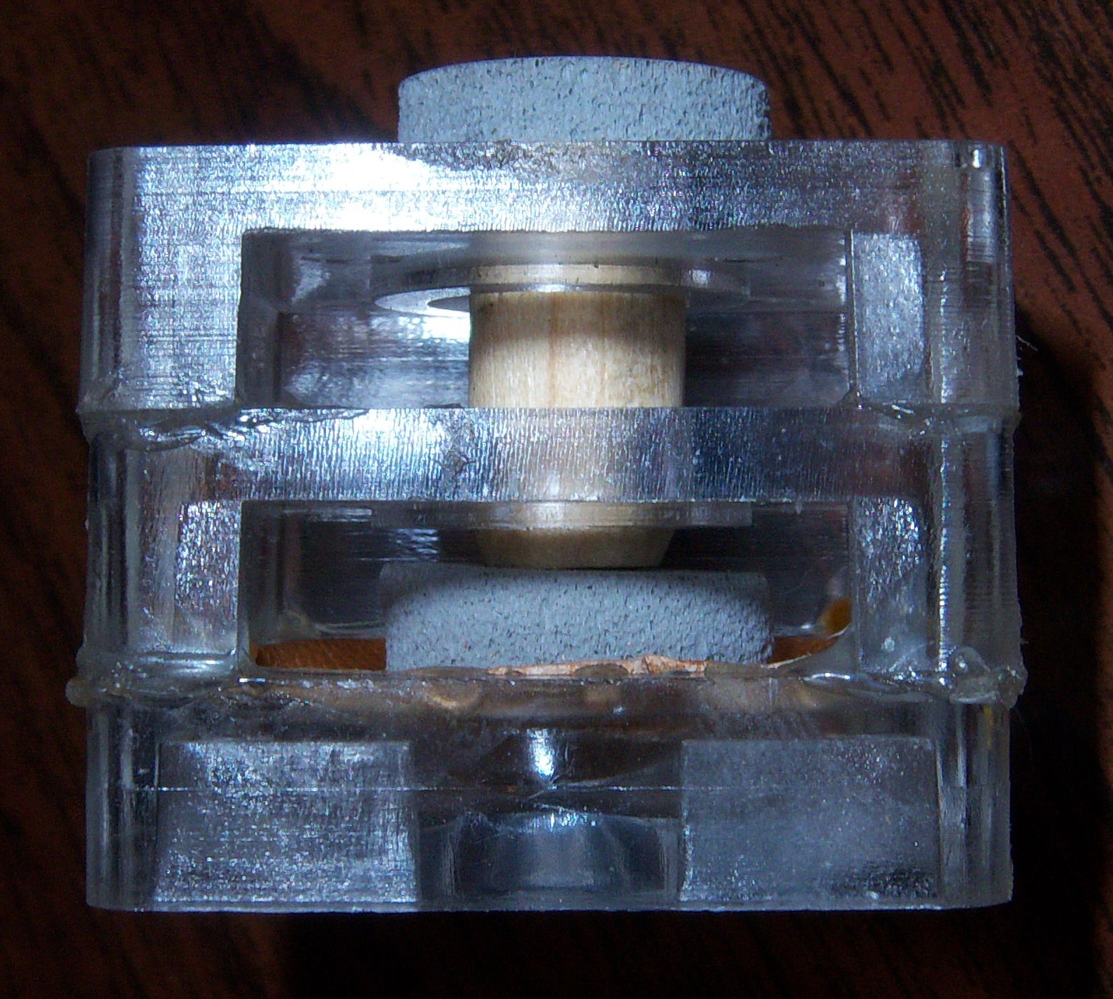
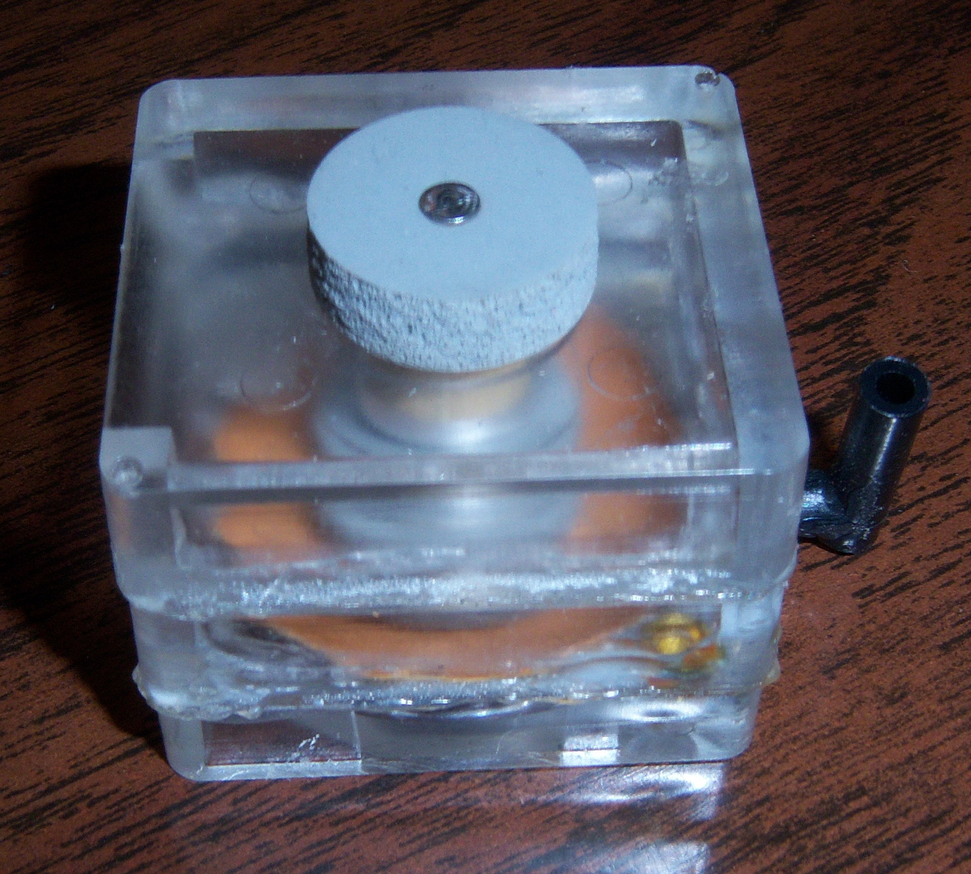
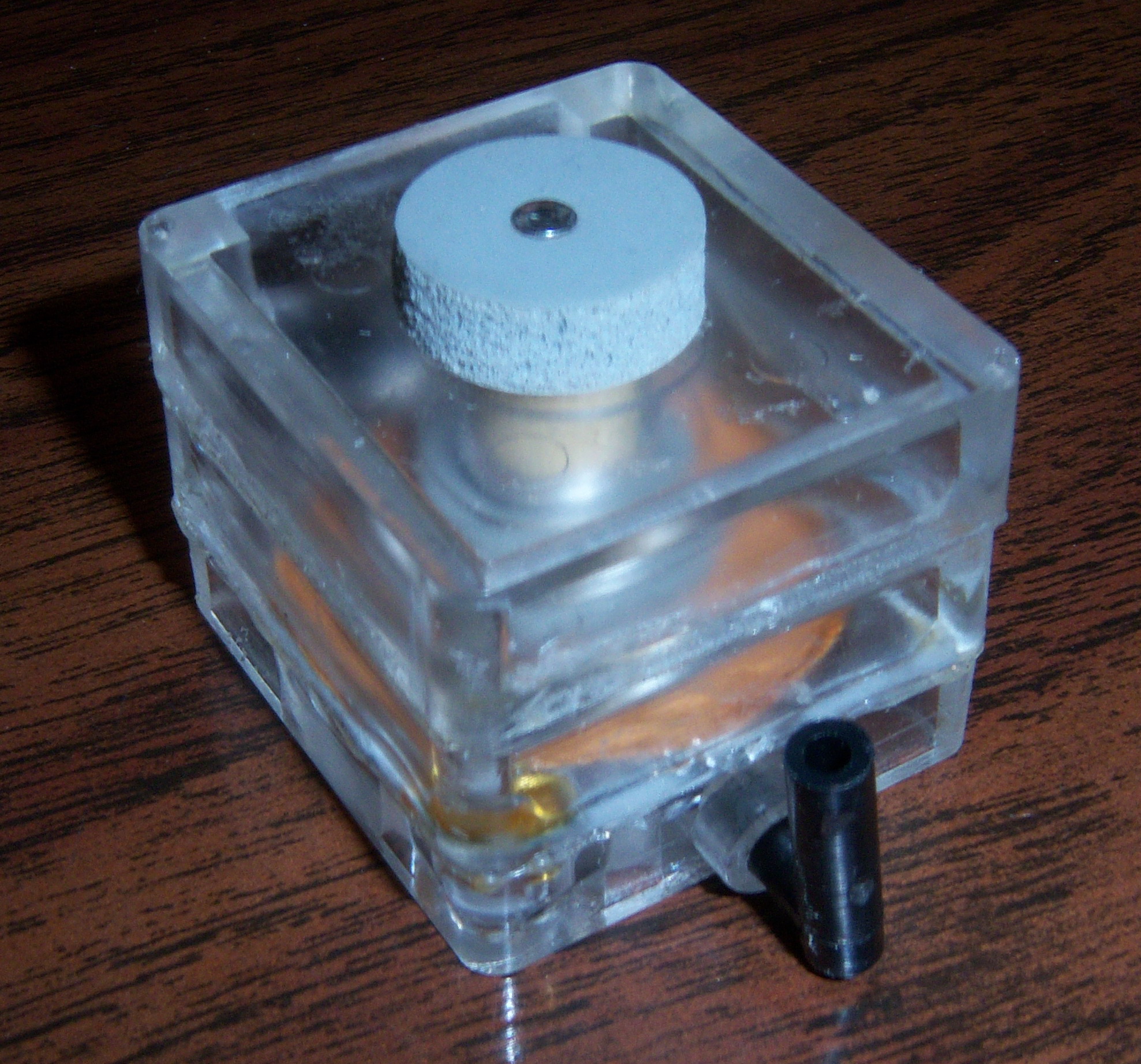
And the Development of a Simple New System While there have been any number of Automatic Shut-Off devices and sequences developed and produced for regular and reproducing player pianos since the early days of electrically driven vacuum pumps (both rotary and turbine), one of the problems has been activating the 'On-Off' switch without using some sort of mechanical linkage. Generally speaking, once the switch has been turned 'On', it's relatively easy to turn it 'Off' at the right time, and this is typically done pneumatically. In other words, a signal from the trackerbar or the take-up spool triggers a valve to turn 'on', and that valve in turn closes a pneumatic which mechanically turns 'off' the power switch. Still, until now all (see Note 1) Auto Shut-Off sequences have required some mechanical action by the user, beyond simply hooking the roll to the take-up spool and pressing an 'On' button, to engage what is often referred to as the "On-and Hold" sequence (see Note 2). (The 'On-and-Hold' sequence is that part of an auto shut-off sequence that keeps the power turned 'on' during both the Play and Rewind cycles. In systems with mechanical linkage, the linkage pushes or pulls a regular toggle switch 'on', and the switch stays in that position until it is pushed or pulled 'off'. So, the 'on-and-hold' action is performed by the switch itself.) It is this 'On-and-Hold' sequence which has always seemed to complicate the otherwise or seemingly simple action of getting a switch to stay 'on' when using something other than a toggle switch. As it turns out, the problem of getting a momentary (or spring loaded) switch to stay 'on' during the Play and Rewind cycles, and to get that same switch to turn 'off' with a signal from the trackerbar isn't really difficult at all. All that's needed is a rather uncommon type of vacuum operated valve, which is known by some as an "Outside Valve". Basically speaking, an 'outside valve' works just the opposite of a normal valve in that when the pouch is relaxed, vacuum is allowed to flow through the valve and into a bellows, causing it to collapse. Then, when the pouch is inflated, the valve changes state, vacuum to the bellows is turned 'off' and atmosphere is allowed to enter the bellows, through the valve, causing it to relax. Below is a diagram that shows all of the components needed to create this simple Auto-Shut-Off system. Below that are a diagram of an outside valve and pictures of an outside valve that I made up this weekend (3/16/13). Following them are explanations of how to install the system and how the system works. 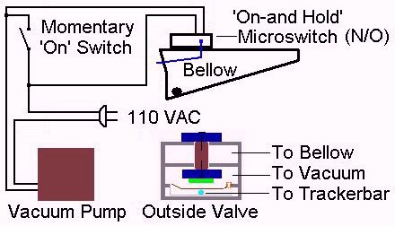 To return to previous location -click here. 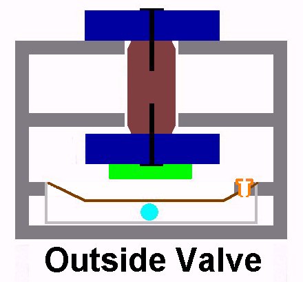
(Simple Installation Instructions) There is only one modification that has to be made to the trackerbar of a player piano with an existing electric vacuum pump. After checking numerous music rolls, it was determined that hole #88 is almost never opened by either the music itself or the extra perforation at the end of the music roll, which are typically used to trigger and automatic rewind device -should one be installed in the player system. (It was also found that holes #1, #2, and #87 are almost always 'opened' by this extra set of perforations which follow the end of the music on the roll. Therefore, it is suggested that the signal tube for the outside valve be connected to hole #88 on the trackerbar. The second modification that has to be made involves providing a vacuum supply for the outside valve and its associated bellow. In testing, it was found that a 3/8" ID supply was more than adequate to operate the valve and bellows without any difficulty. The supply hose can be connected anywhere in the system where there is an unregulated vacuum source that is available in both the Play and Rewind modes. (In other words, it should not be connected to the stack or the vacuum supply that operates that air motor.) Lastly, one leg of the AC line cord that leads to the vacuum pump has to be cut and auto shut-off circuit has to be connected in series with that cut line. (see 'Wiring Diagram') Note: In existing systems that already have a voltage controller (to control the speed of the vacuum pump motor), the controller is already wired in series with the AC line voltage and the vacuum pump motor. So, in reality you're only adding one component to this series circuit. However, in such systems, the 'on-off' toggle switch on the controller must be left in the 'on' position for the auto shut-off system to work properly. Also, in systems with only an 'on-off' toggle switch to tunr the pump 'on' or 'off', it is not necessary to remove the existing switch, but it is recommended to do so in order to avoid confusion. Although the diagram is fairly self-explanatory, here's the explanation of how this all works. The purpose of the Momentary 'On' Switch, which is wired in parallel with the 'On-and-Hold' Microswitch, is to apply 110 volts AC to the Vacuum Pump. Once the pump comes on, vacuum is applied to the 'Outside Valve', which in turn (due to the design of the valve) causes the bellows to collapse. As the bellows closes, a protrusion on the side of the bellows activates the microswitch, completing a path for the voltage, which will remain intact until the bellows relaxes. As explained earlier, the outside valve works differently than a normal player piano valve in that when there is no trigger signal from the trackerbar, vacuum is allowed to flow through the valve, which in turn collapses the bellows to which it is attached. Therefore, once a music roll is installed and hooked to the Take-Up Spool and the Player/Rewind lever is moved to the 'Play' position, the system is ready to be started. This action closes the #88 note hole. The hose that's connected to the #88 note hole on the trackerbar is rerouted to the 'outside valve'. Therefore, power continues to be applied to the vacuum pump as long as there is paper covering the trackerbar, which is always the case until the end of the Rewind cycle. At the end of the Rewind cycle, hole #88 opens, which causes the outside valve to change state. When this happens the vacuum which held the bellows closed is turned off and atmosphere is allowed to flow into the bellows and the bellows relaxes (or returns to the open position) [See Note 3]. As that happens, the microswitch returns to its 'normally off' position, which in turn removes power from the vacuum pump motor. In subsequent tests, it was found that the #88 hole in the trackerbar would sometimes be opened by perforations at the end of the music roll or by actual playing notes within the music roll. Obviously, this was a problem since the system would shut off as soon as the #88 hole was opened -even if only for a moment. So, to solve that potential problem, a 'bleed' of sorts was installed between the valve and the bellow. The bleed is actually a constriction, or a small hole, through which air is allowed to travel. When properly sized, the bleed increases the amount of time it takes for the bellows to open after the valve changes state. So, even if the #88 hole is opened momentarily, and the valve chages state, the bellows won't open fast enough to change the state of the microswitch. The bleed was sized such that it now takes 1-2 seconds for the bellows opens enough to change the state of the microswitch. Unfortunately, this change created a minor problem in that the bleed also increased the amount of time required to collapse the bellows and activate the microswitch. This problem was solve by creating a mini flap vlave. Basically speaking, it's a piece of tan pneumatic leather that's positioned over the opening through which the air passes that deflates and inflates the bellow. However, this flap valve has a tiny hole in it. When vacuum is initially applied to the valve, the air being sucked out of the bellows pushed the flap valve off of its seat and the bellows collapses quickly and stays collapsed as long as there is vacuum applied to the valve. When the valve changes state as atmosphere tries to equalize the vacuum in the bellows, it has to go through the tiny hole in the flap valve, which dramatically increases the amount of time it takes the bellows to open (or relax). And, therefore, it increases the amount of time is takes for the microswtich to open, which in turn shuts off the vacuum pump and completes the cycle. 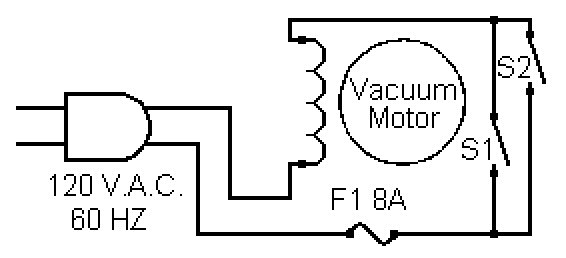 To return to previous location -click here. NOTE 1: Having invented and installed an Auto Shut-Off system with a 'push-button' momentary 'on' electric switch into a Francis Bacon upright back in 1996, I know that such systems do exist. Other auto shut-off systems I have encountered have involved such things as latching relays, electro-magnets, and solenoids of various types to perform the initial action of turning the power 'on'. In such cases, all of those systems involved a valve and a bellows to turn the power 'off' at the end of the rewind cycle. Then with the invention of player pianos with electric roll drive mechanisms, the 'push-button' start feature became very common. To return to previous location -click here. NOTE 2: Player Piano Co, in Wichita, KS came out with a clever idea for an Auto Shut-Off device which it successfully marketed for many years. It is often referred to as a "Slap-Off" type of auto shut-off device because it is the action of the music roll spinning at the end of the Rewind cycle and the End Tab hitting a metal tongue which 'slaps' the electric switch to the 'Off' position. The electric switch is mechanically turned 'on' by pushing a button which overcomes the force of a small magnet and at the same time resets the metal tongue so it will respond to the 'slap' of the end tab, and turn the switch back 'off' at the end of the rewind cycle. To return to previous location -click here. NOTE 3: In real time testing, it was discovered that in order to be able to place the 'valve/bellow/microswitch' component "anywhere" in the piano, a small spring needed to be installed on the hinged end of the bellows to 'push' it open after the vacuum was turned 'off'. This modification allowed the device to be mounted upside-down or sideways without having to be concerned about the weight of the movable board preventing the bellows from opening fully. |

![]() ..To
The Top of this Page . . . . . . . . . . .
..To
The Top of this Page . . . . . . . . . . . ![]() ..To The HOME Page
..To The HOME Page
|
Since "Player-Care" is an internet business, I prefer that we correspond via E-Mail (click here to fill out the 'Request Form'). However, if I'm not in the middle of some other activity, you can reach me at 732-840-8787. But please understand that during the hours from 8AM-5PM EST (Mon-Sat), I'm generally quite busy. So, I probably won't answer the phone. If you get the answering machine, please leave a detailed message stating the reason for your call. Also, repeat your name and phone number clearly and distinctly. By necessity, I prioritize everything in my life. And, if you call and just leave your name and number, and ask me to call you back, it might be a day or two before I return your call. Why? Because I don't know why you want me to call and I might not be prepared to assist you in an effective and efficient manner. If you leave me an E-Mail address (which I prefer), spell it out phonetically. The more you do to help me, the more I can help you in return. Don't rush. You have four minutes to record your message. |
|
407 19th Ave, Brick, NJ, 08724 Phone Number 732-840-8787 (Voicemail Only, No Texts) |