Home Manuals Supplies Search Consult Contact Testing Service


Angelus/Amphion Action in a
Marshall and Rose (London)
Expression Player Piano

My Initial Observations After
Seeing The Pictures Below

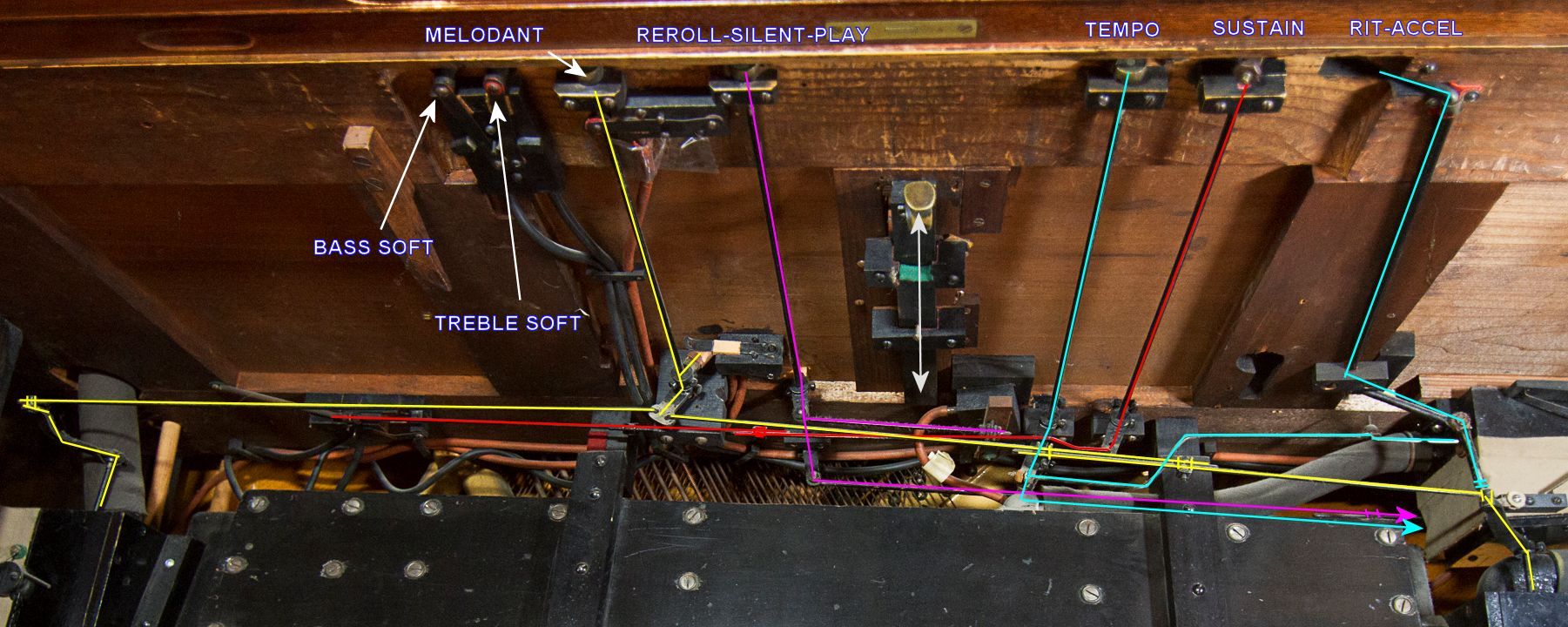
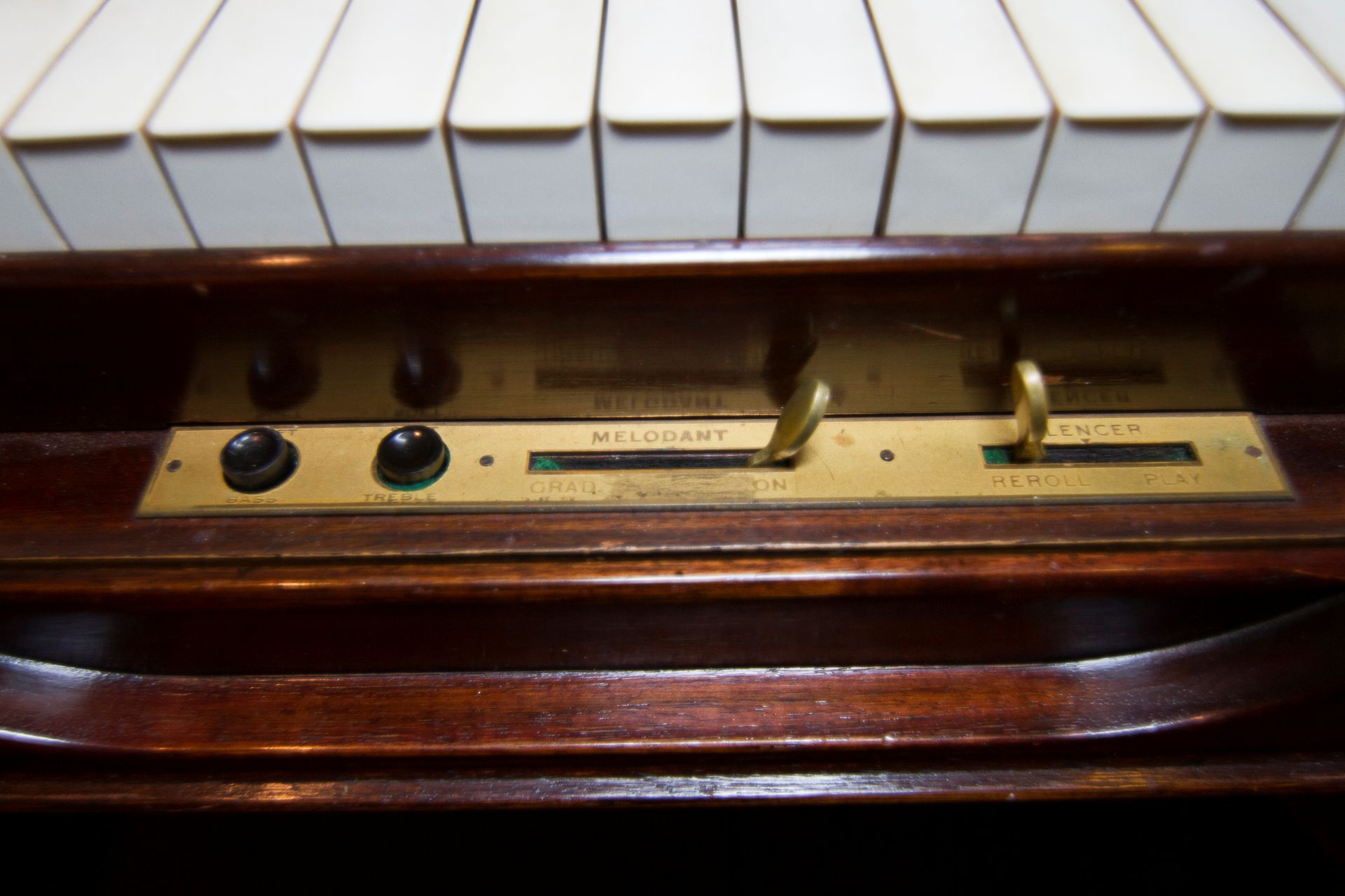
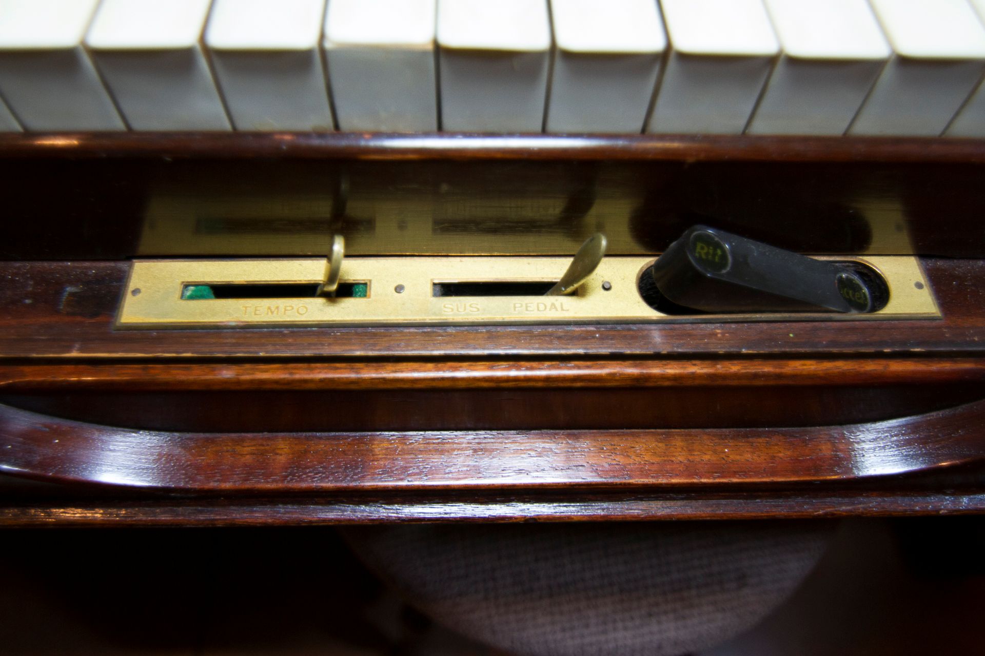
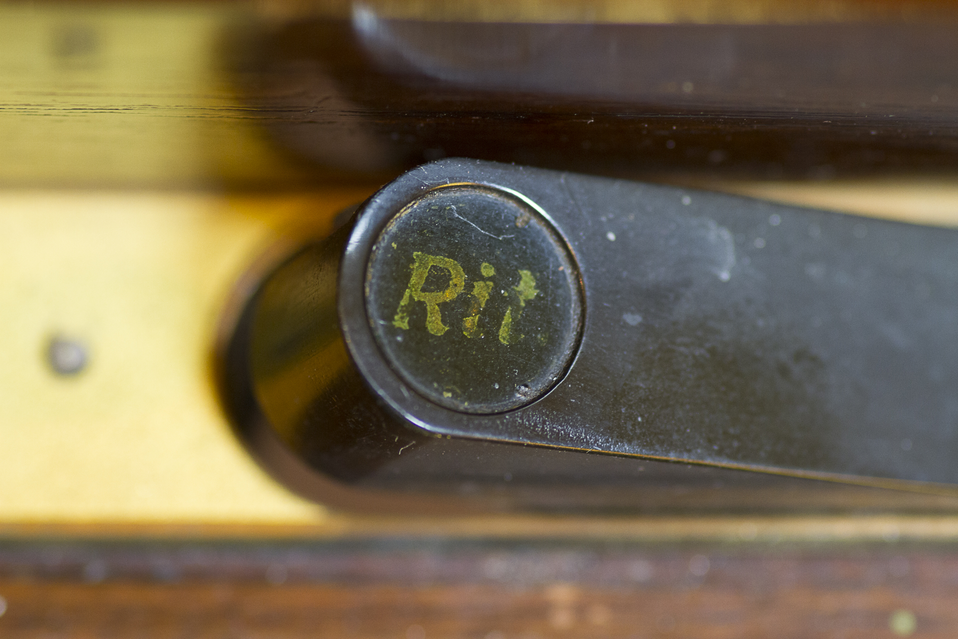
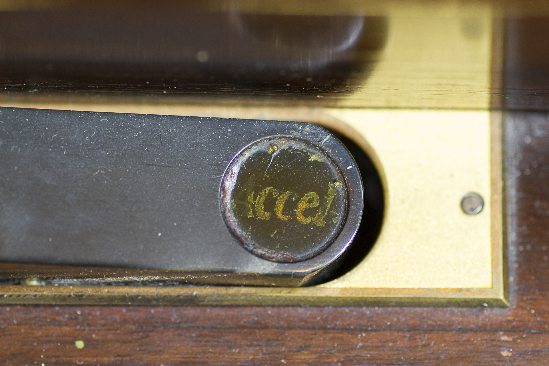
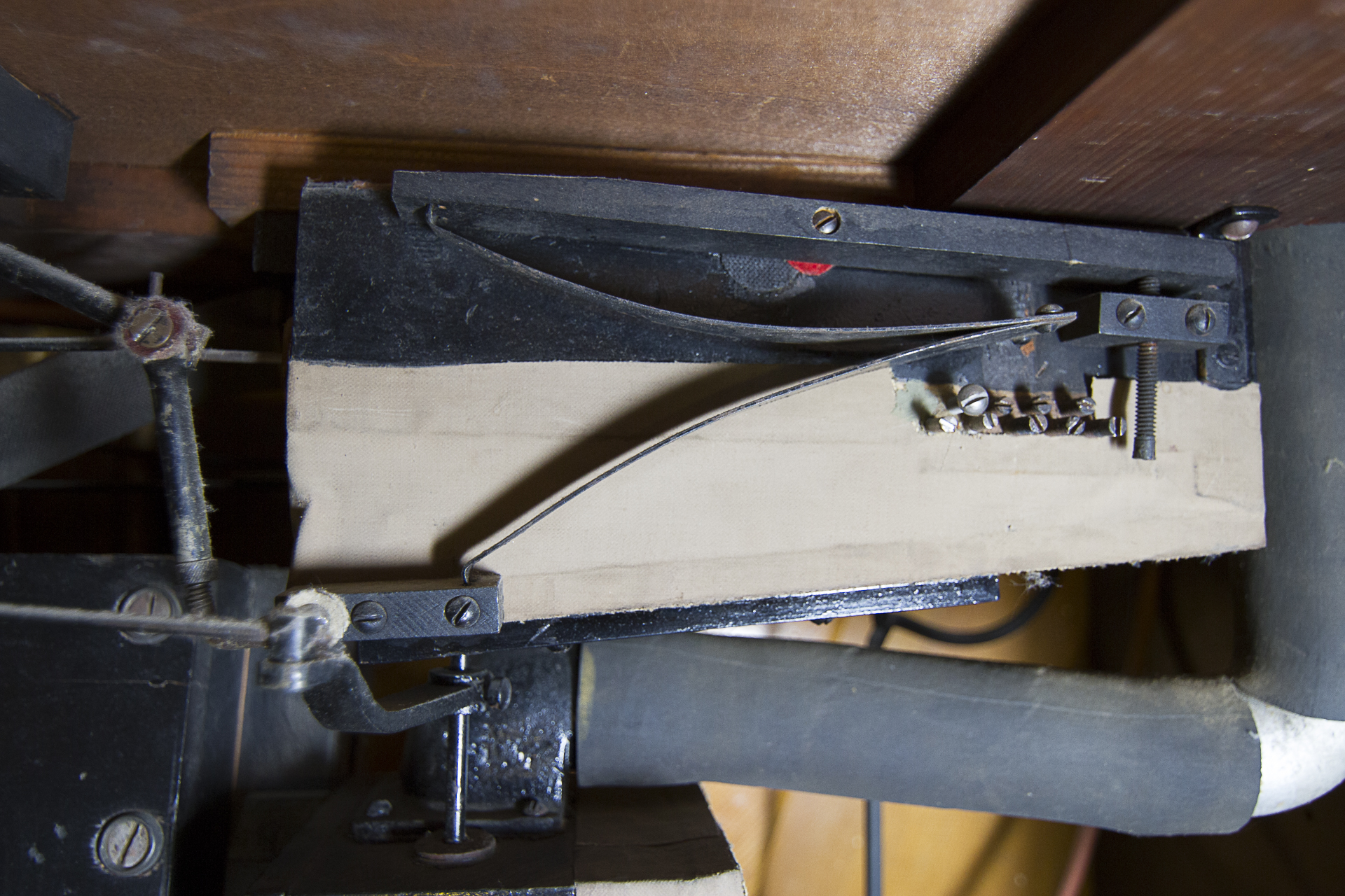
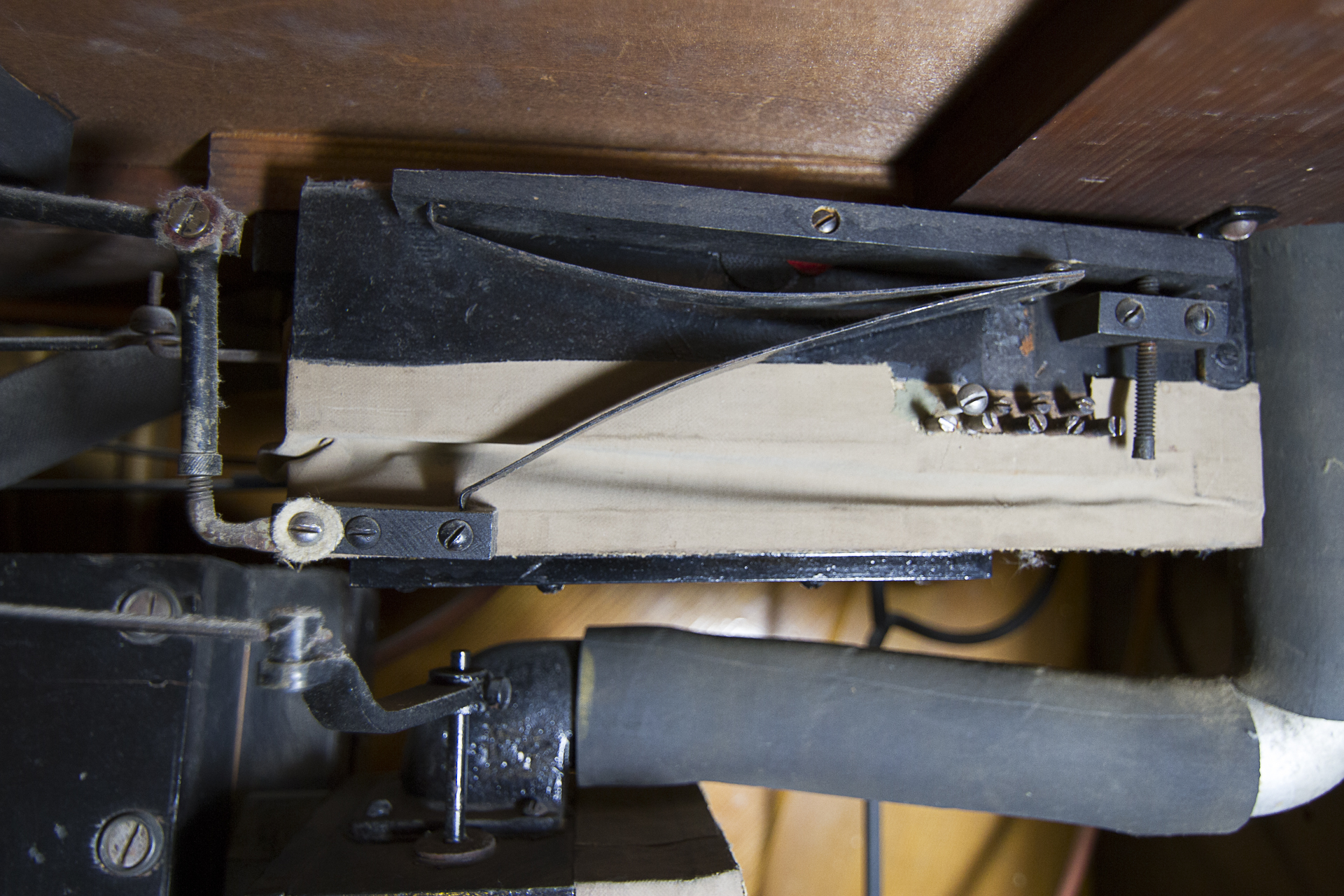
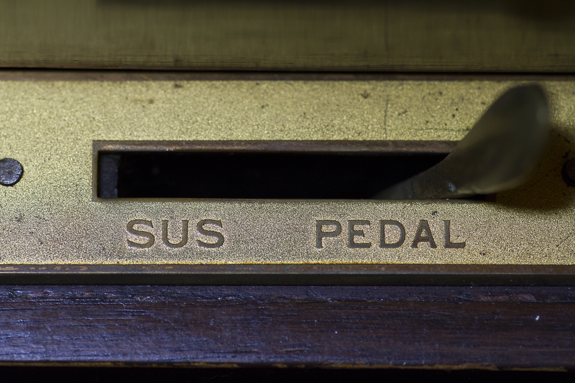
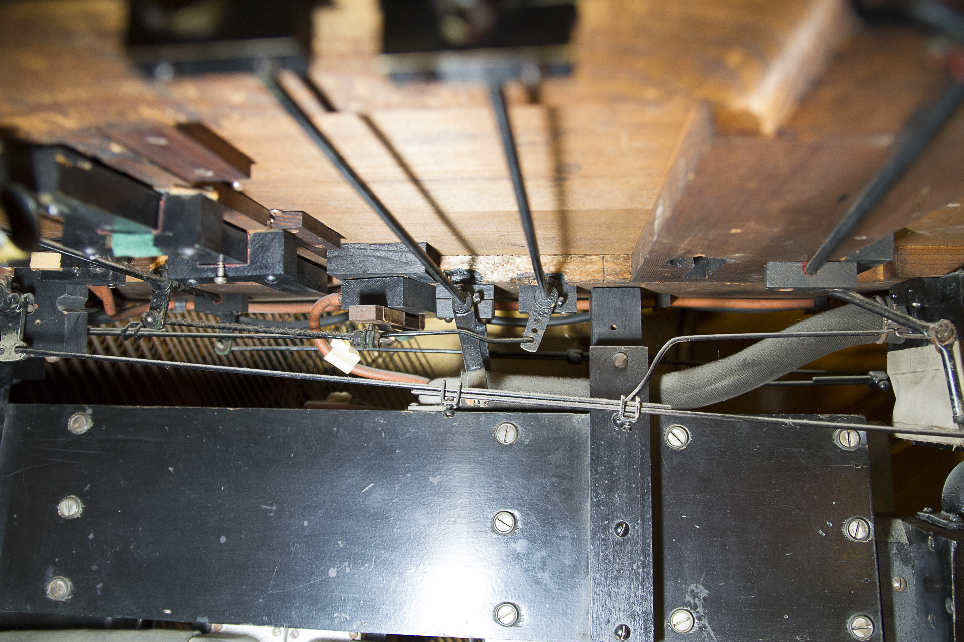
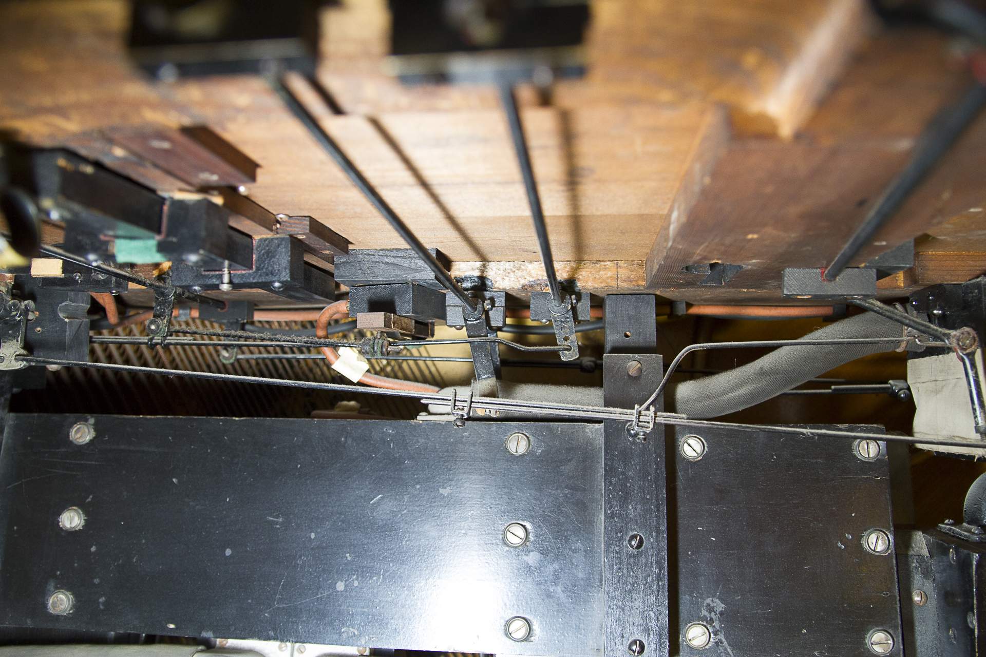
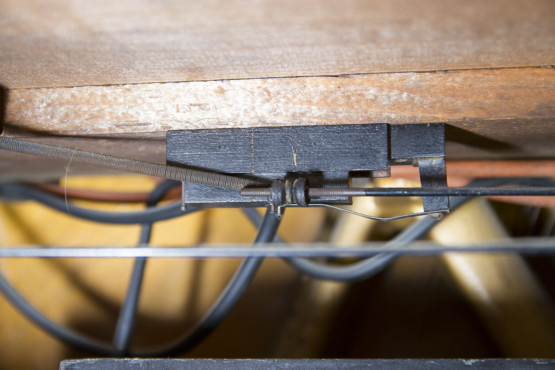
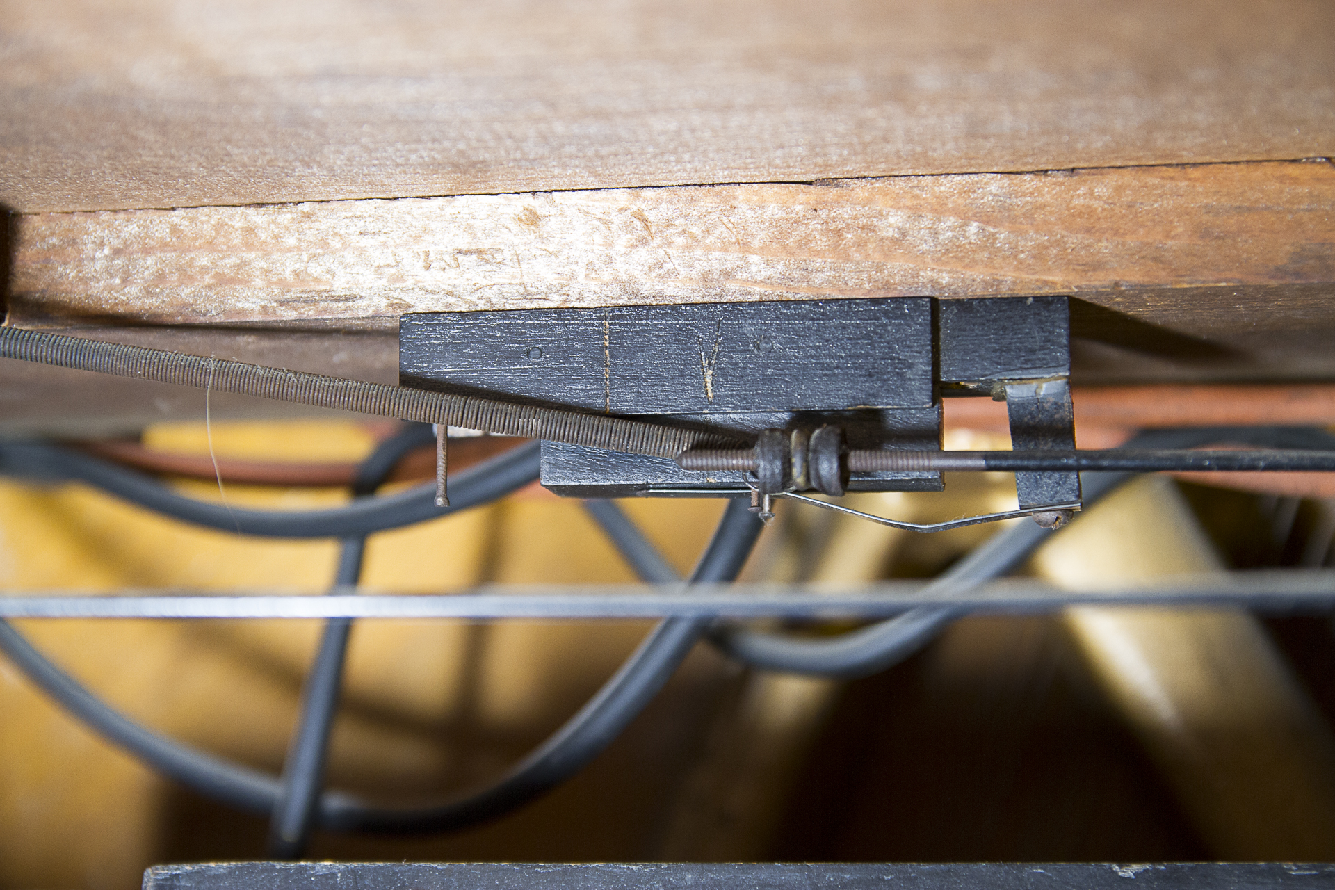
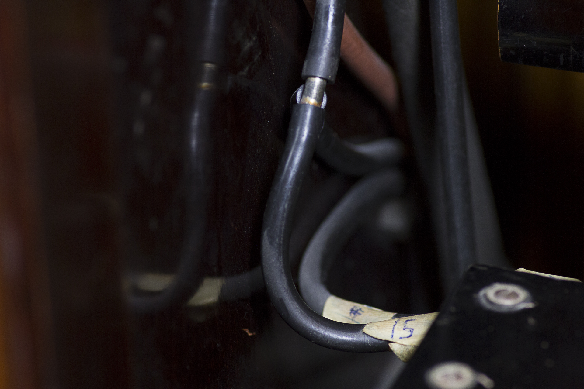
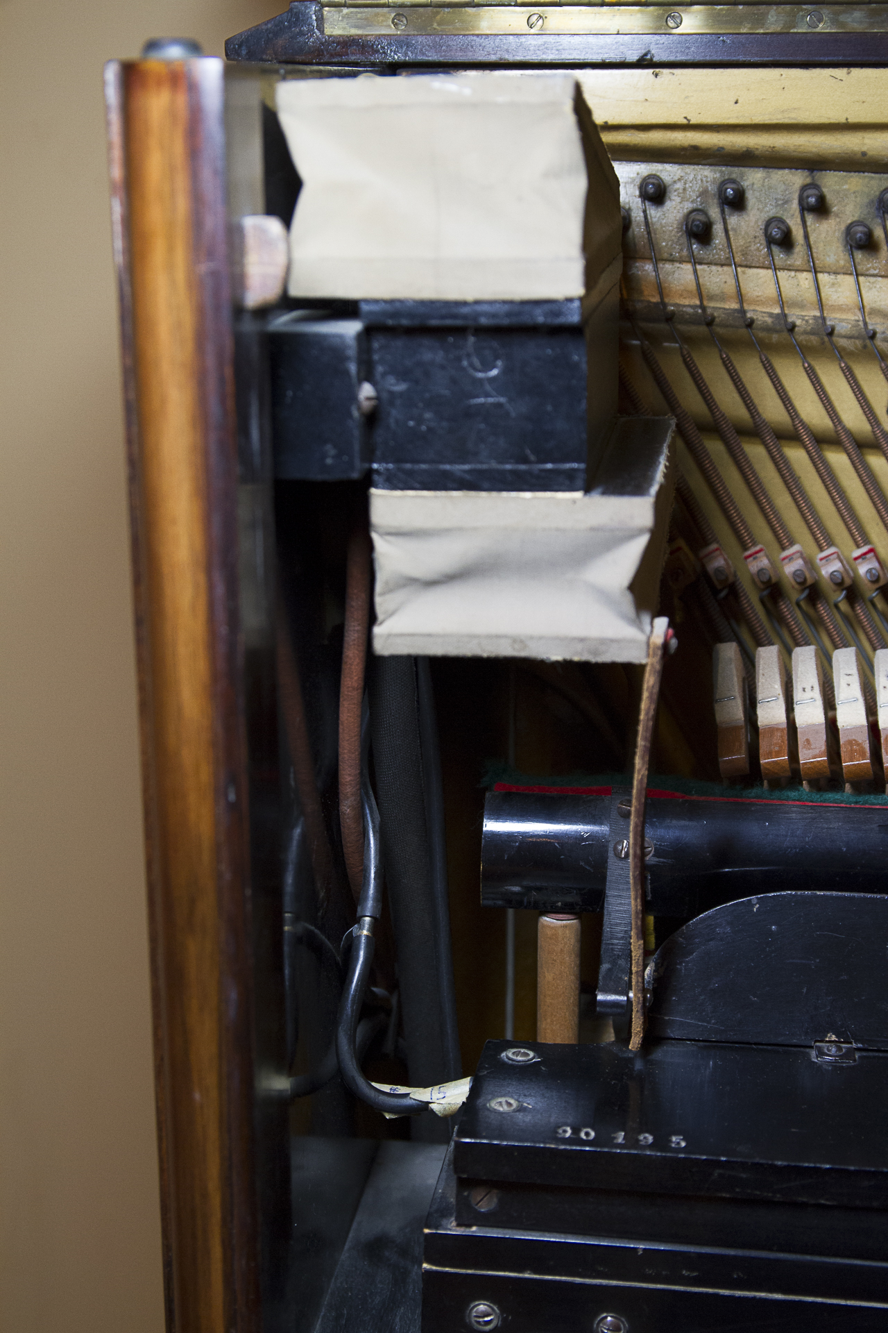
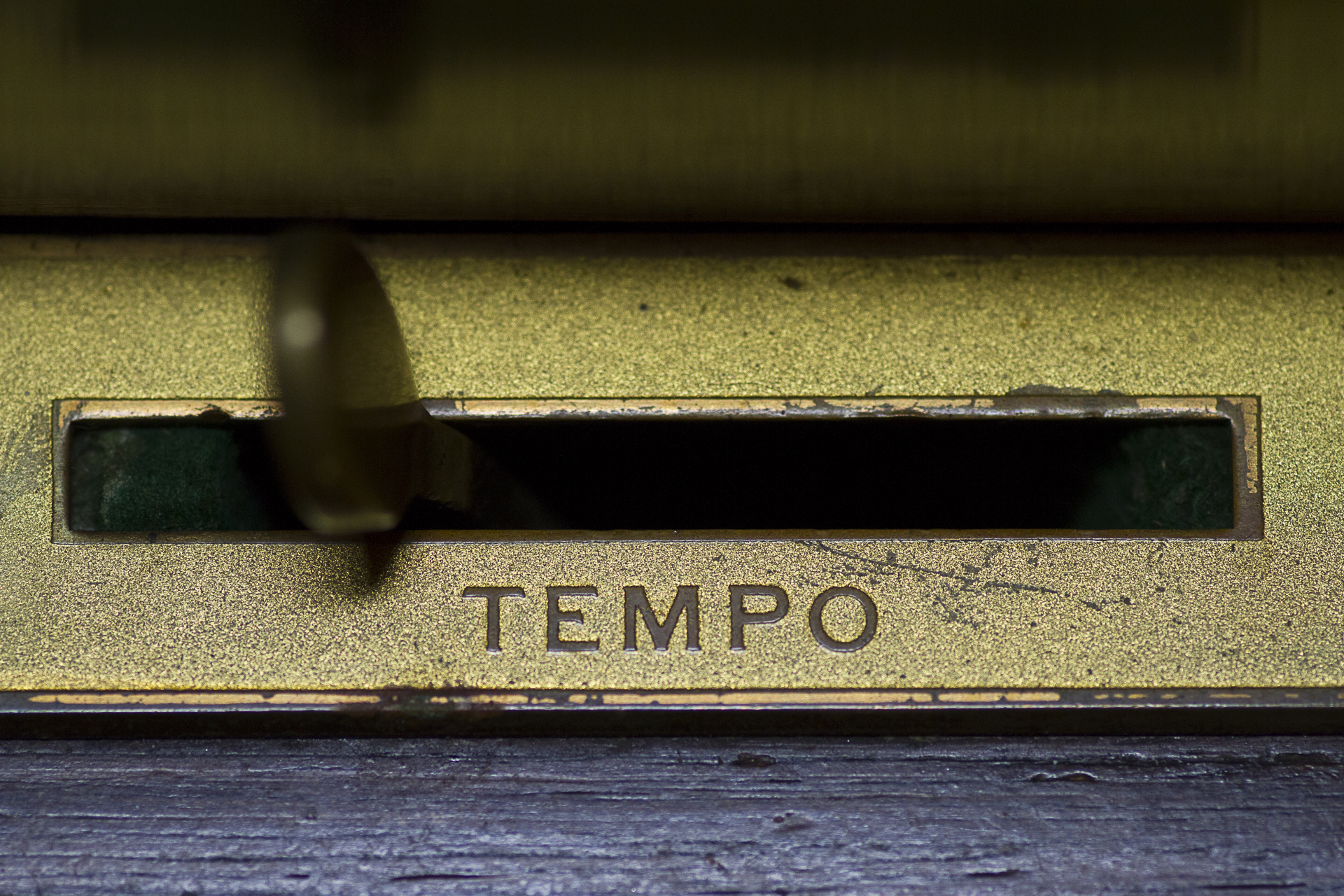
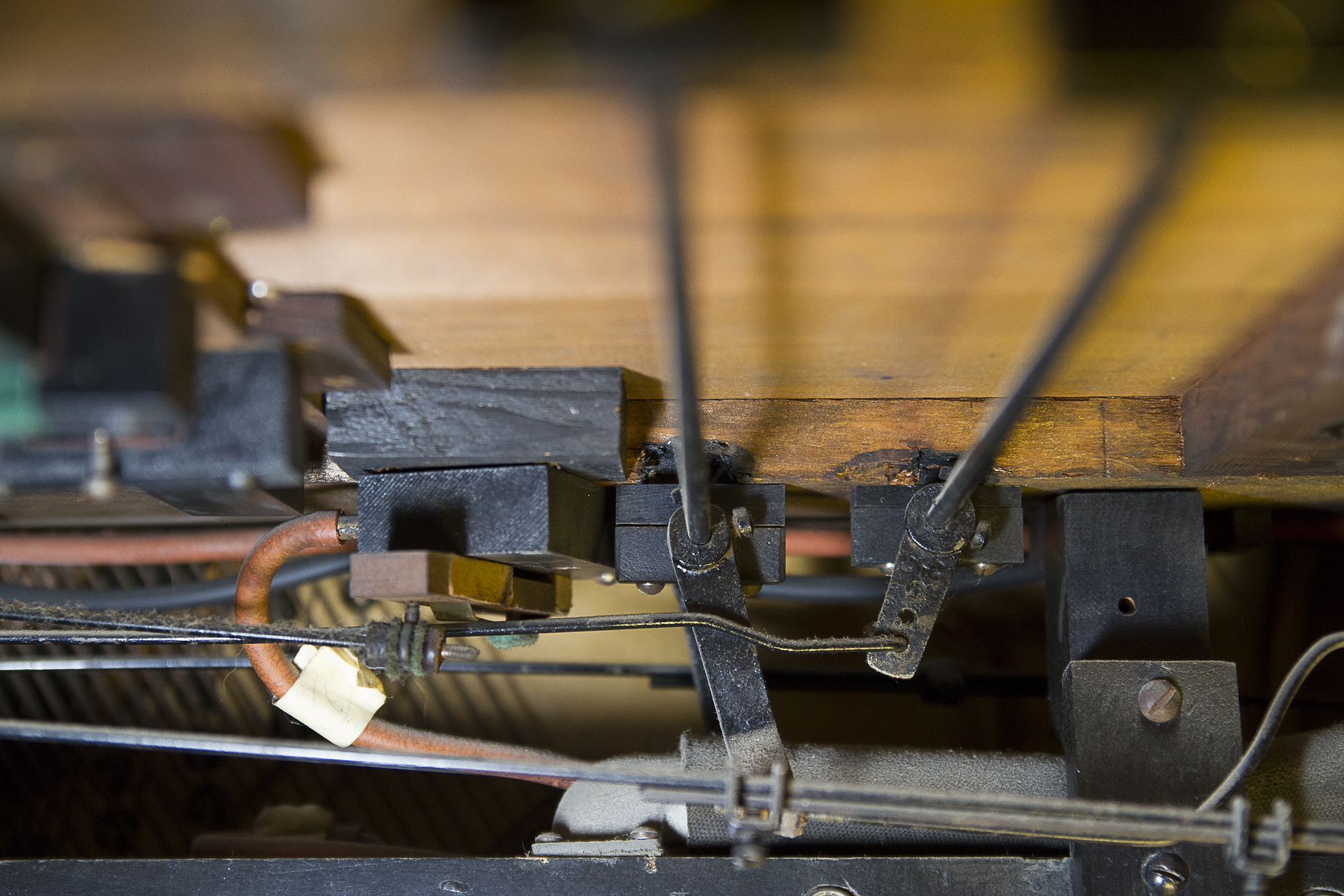
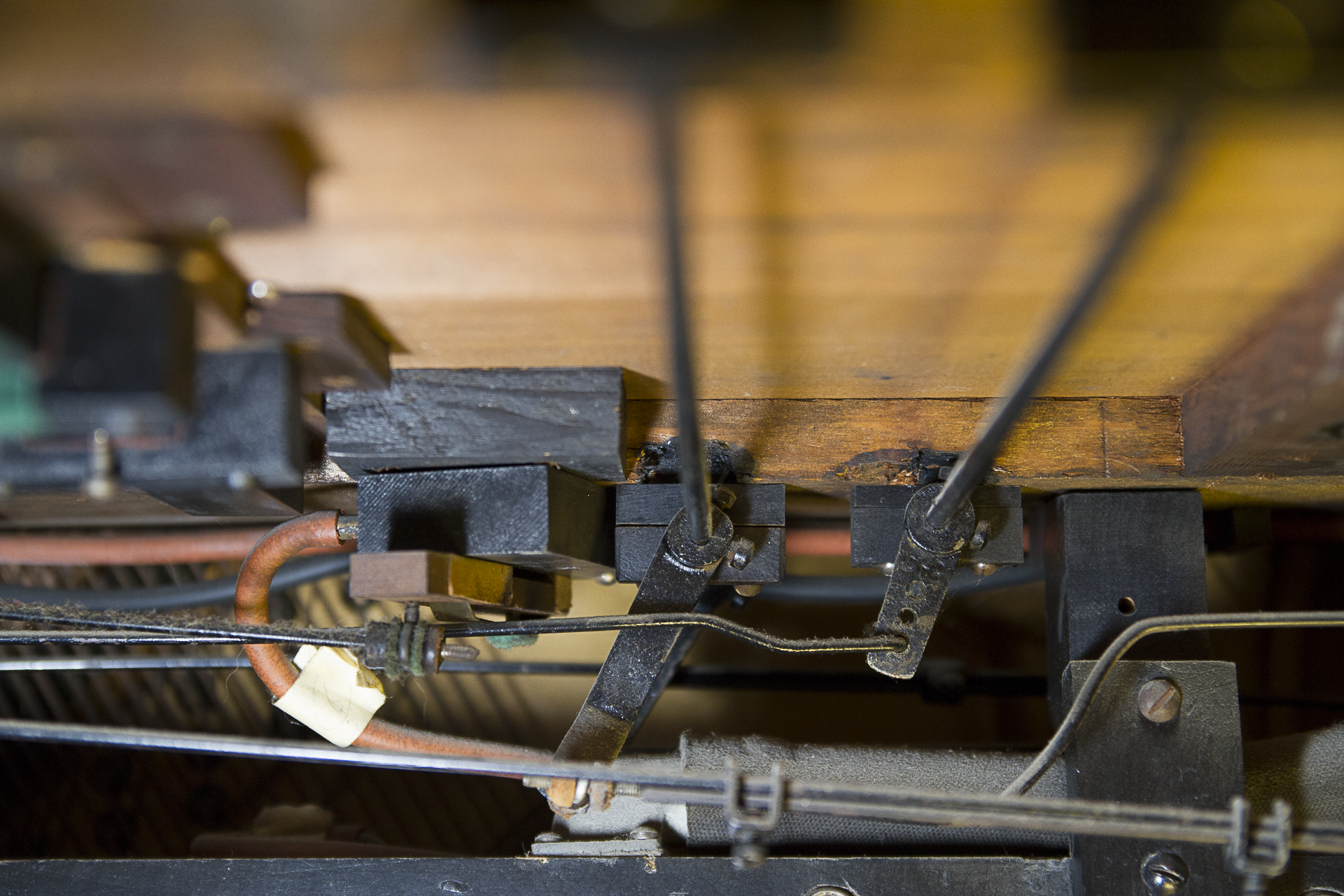
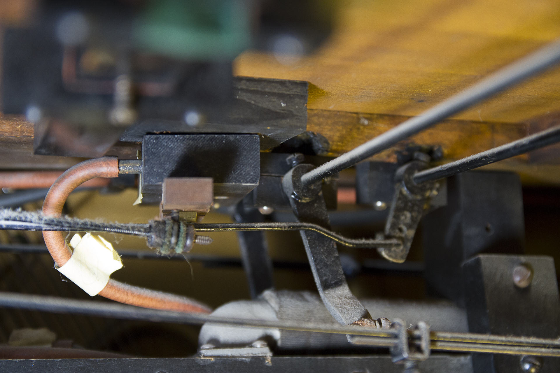
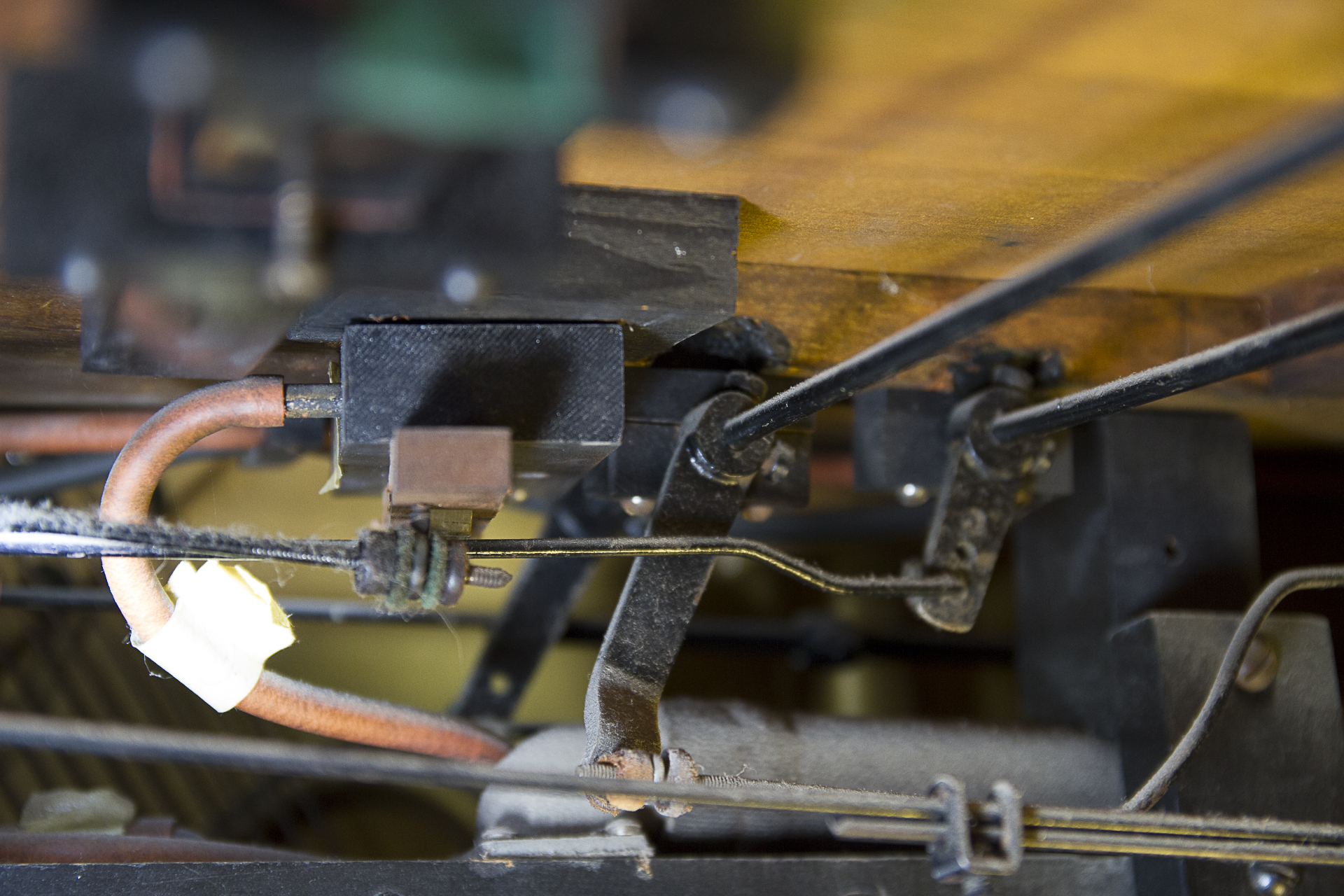
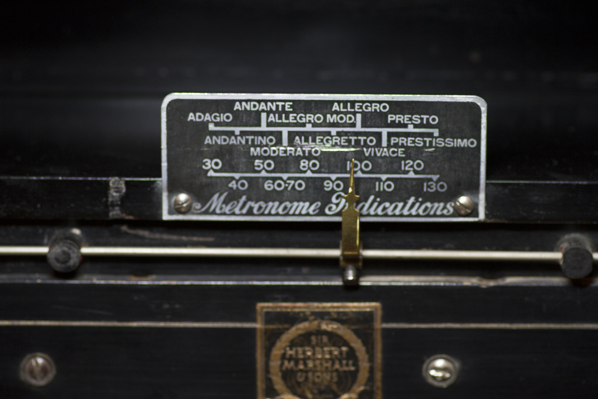
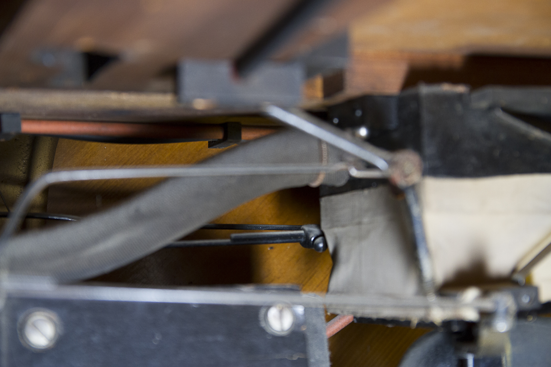
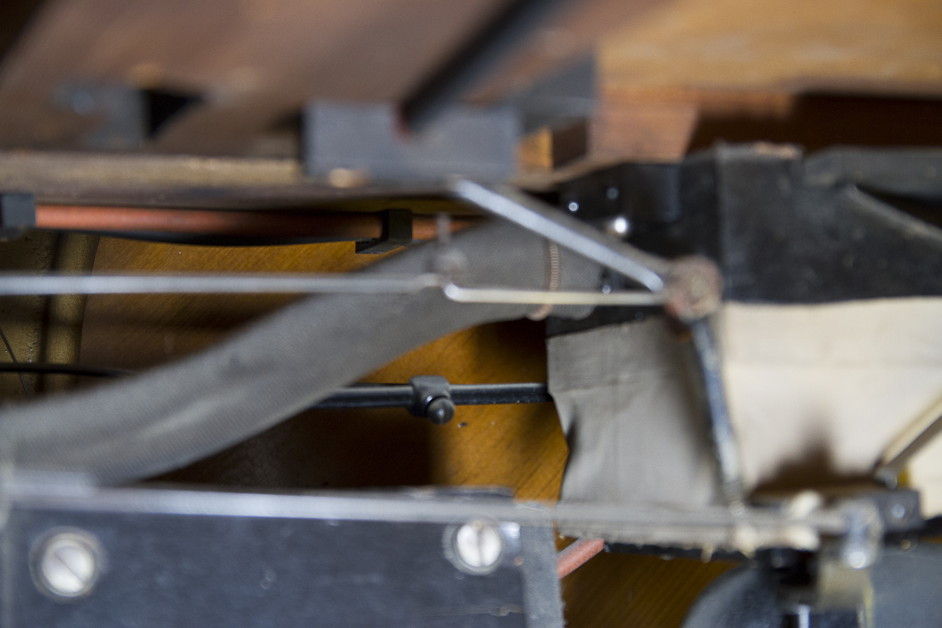
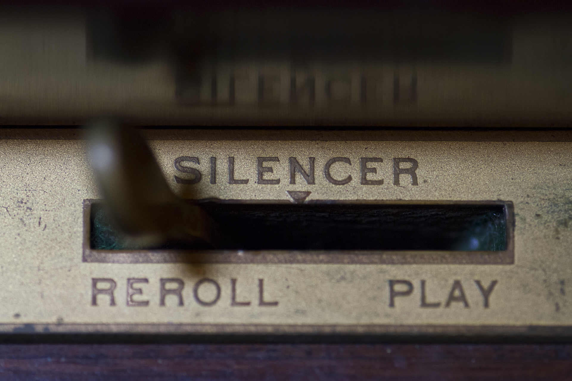
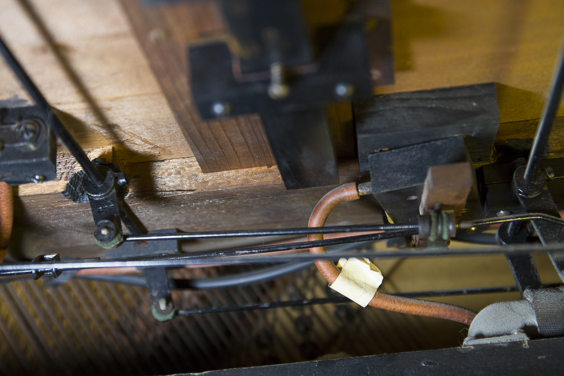
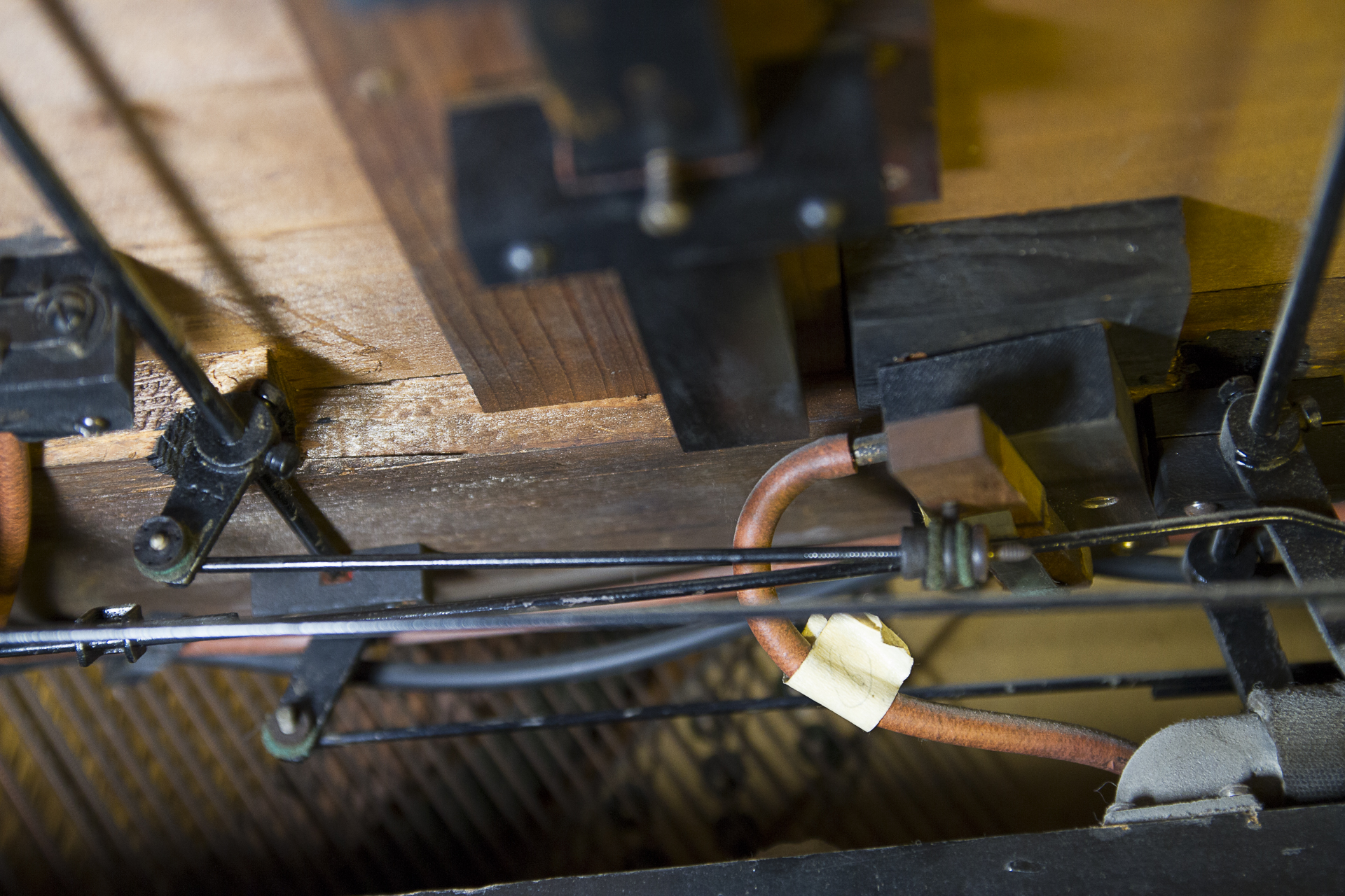
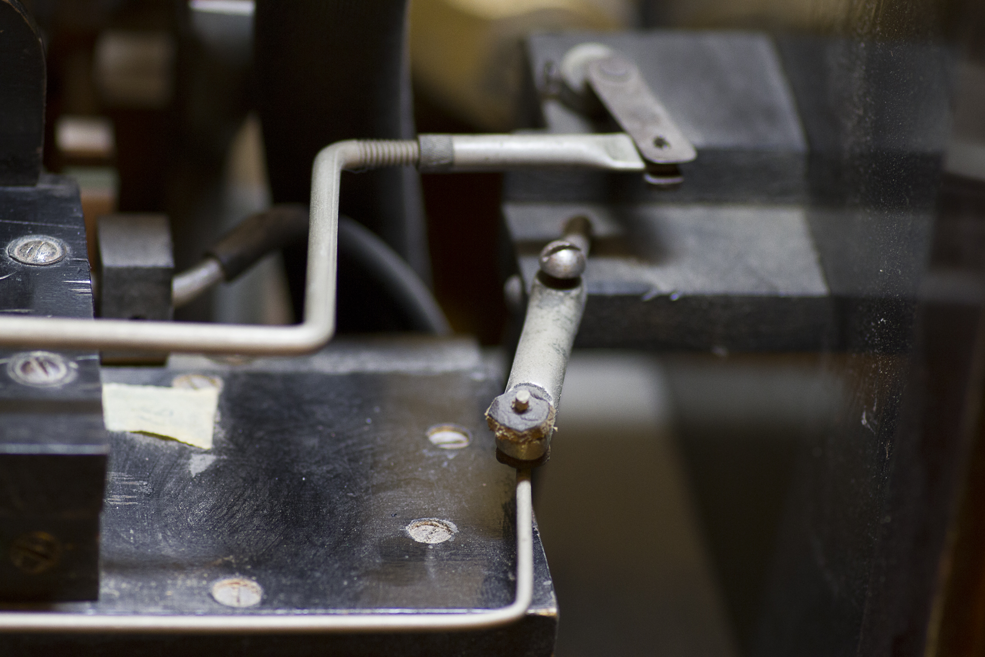
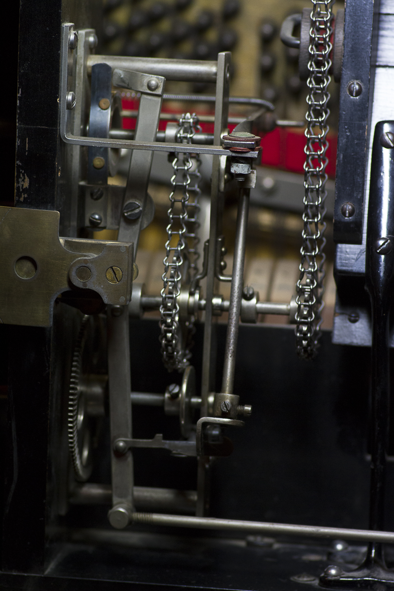
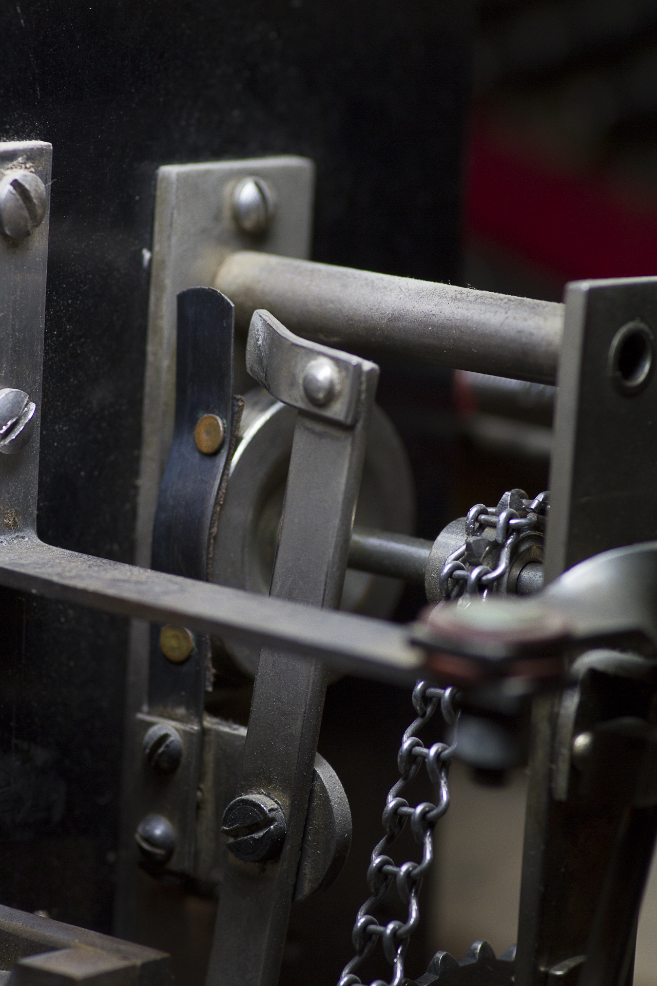
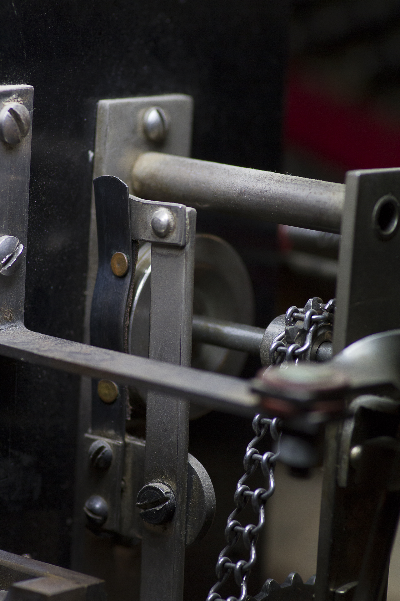
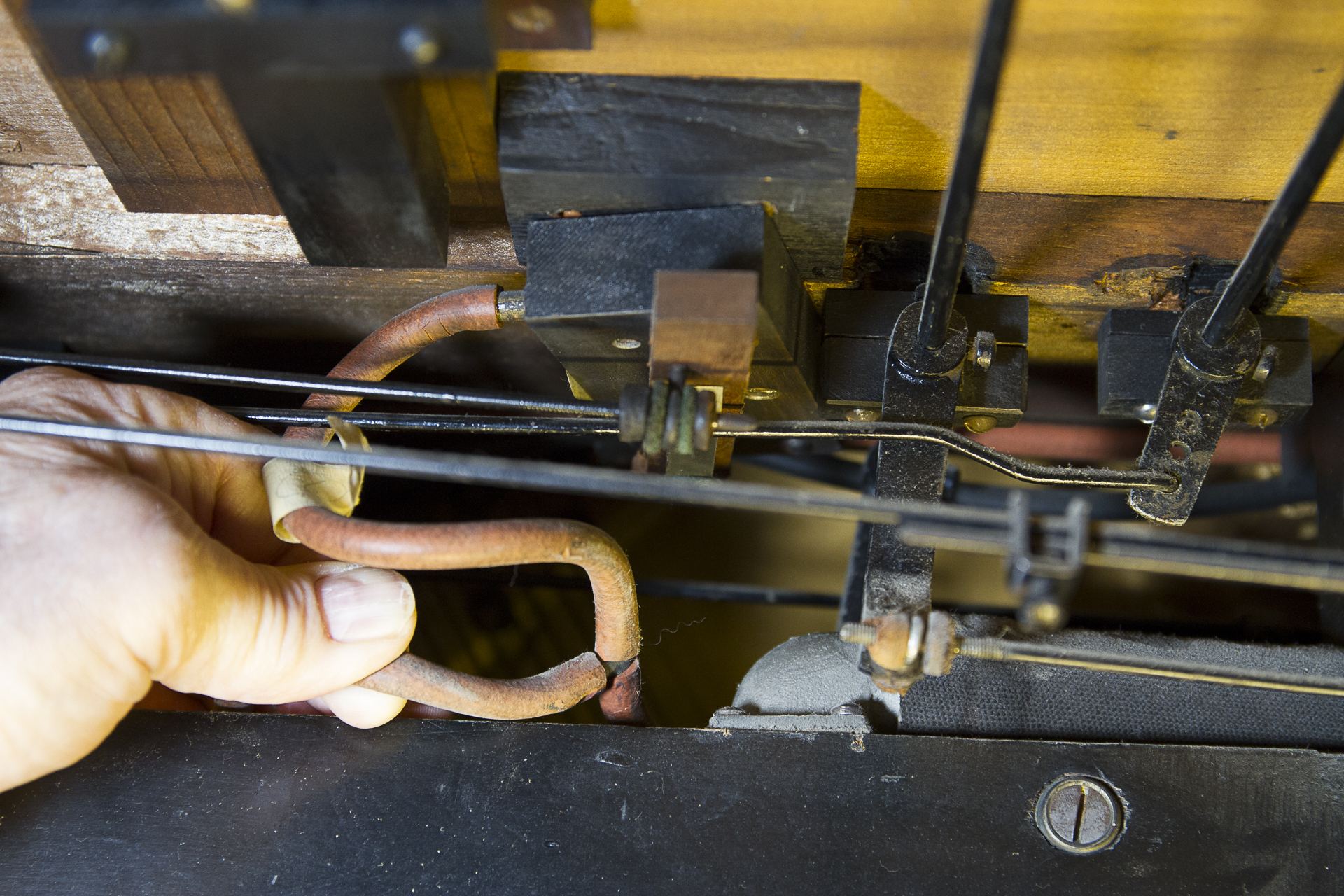
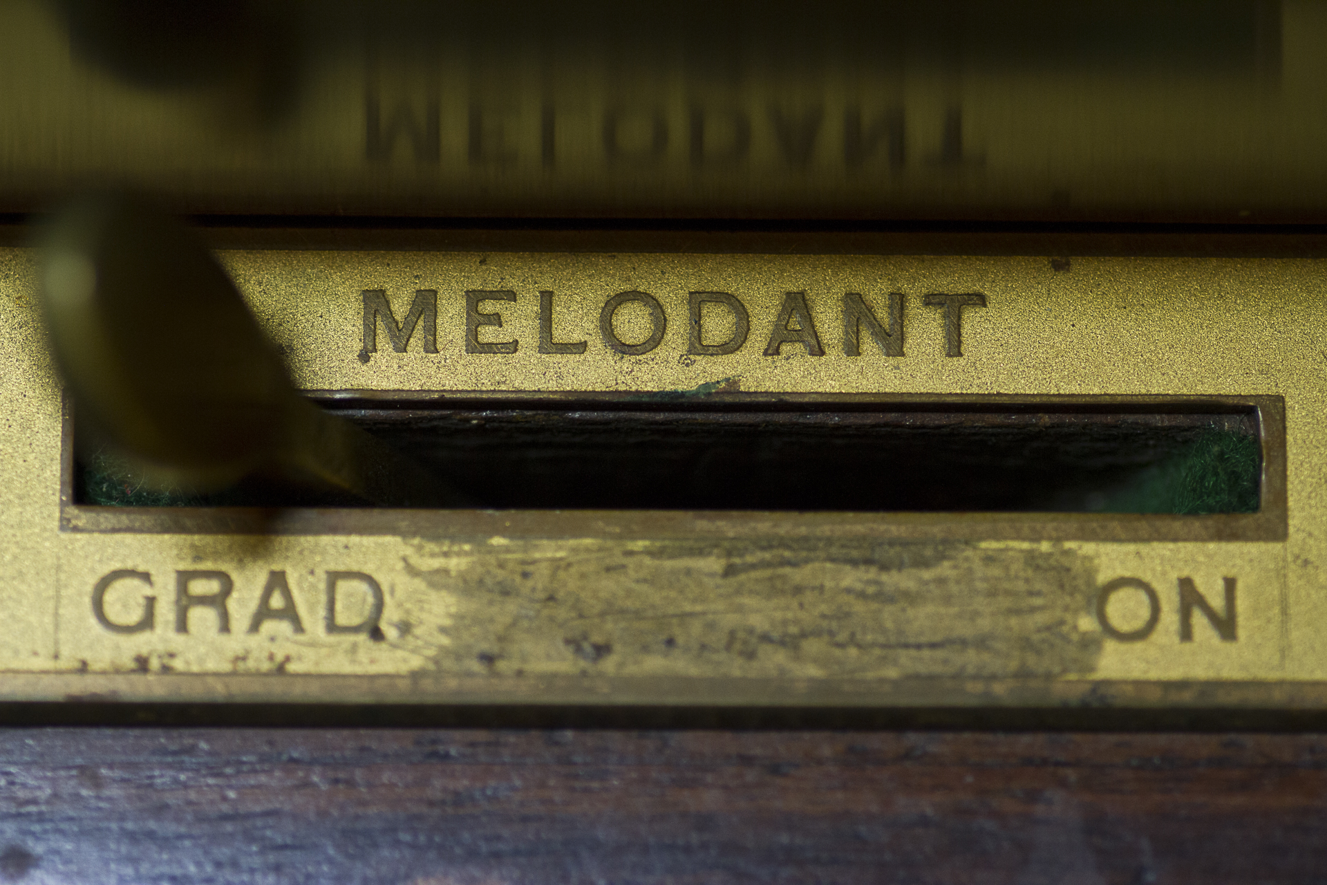
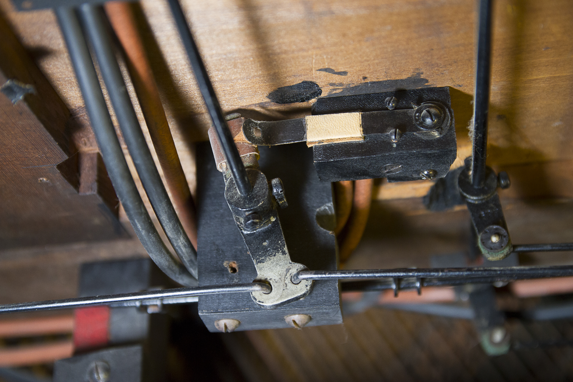
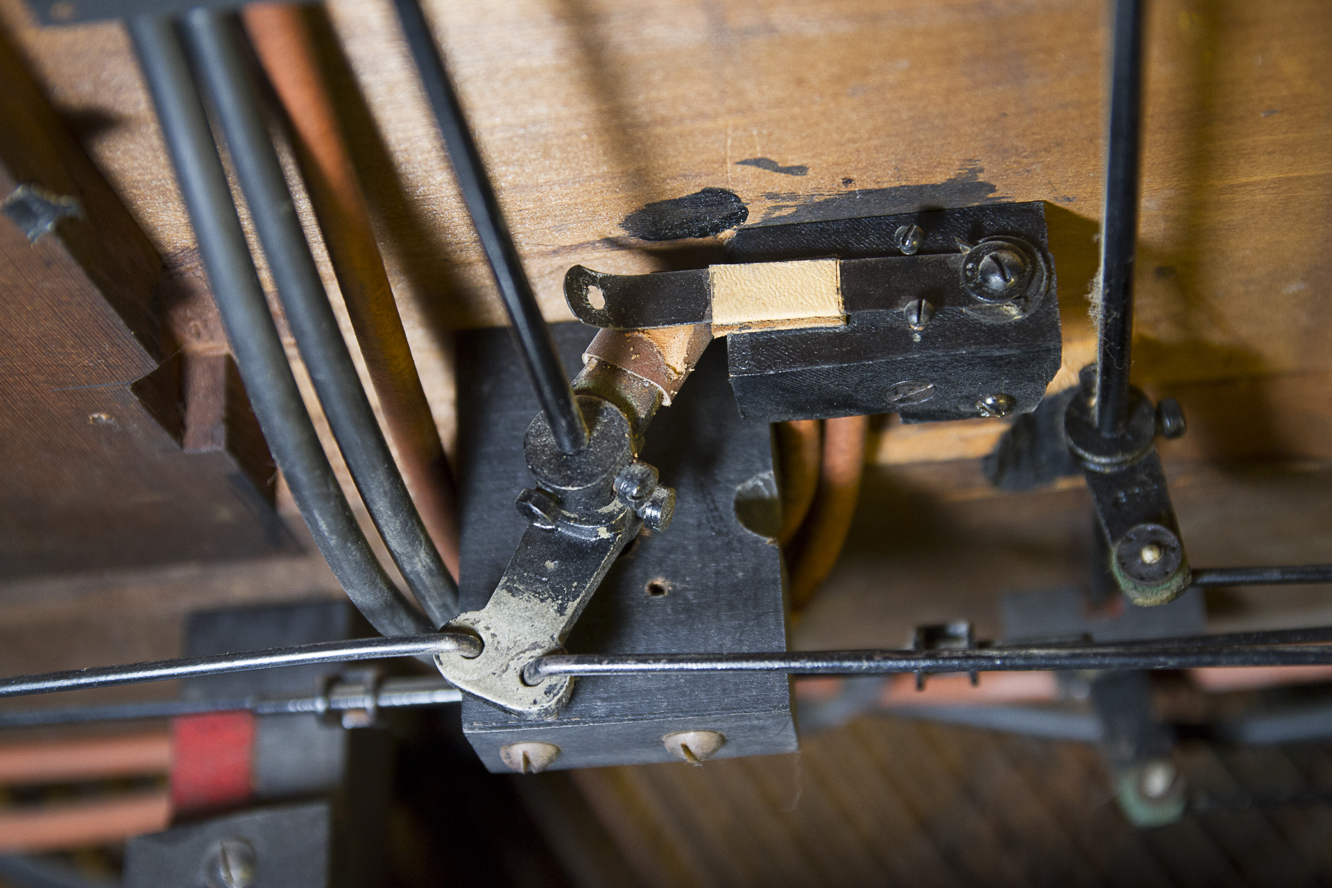
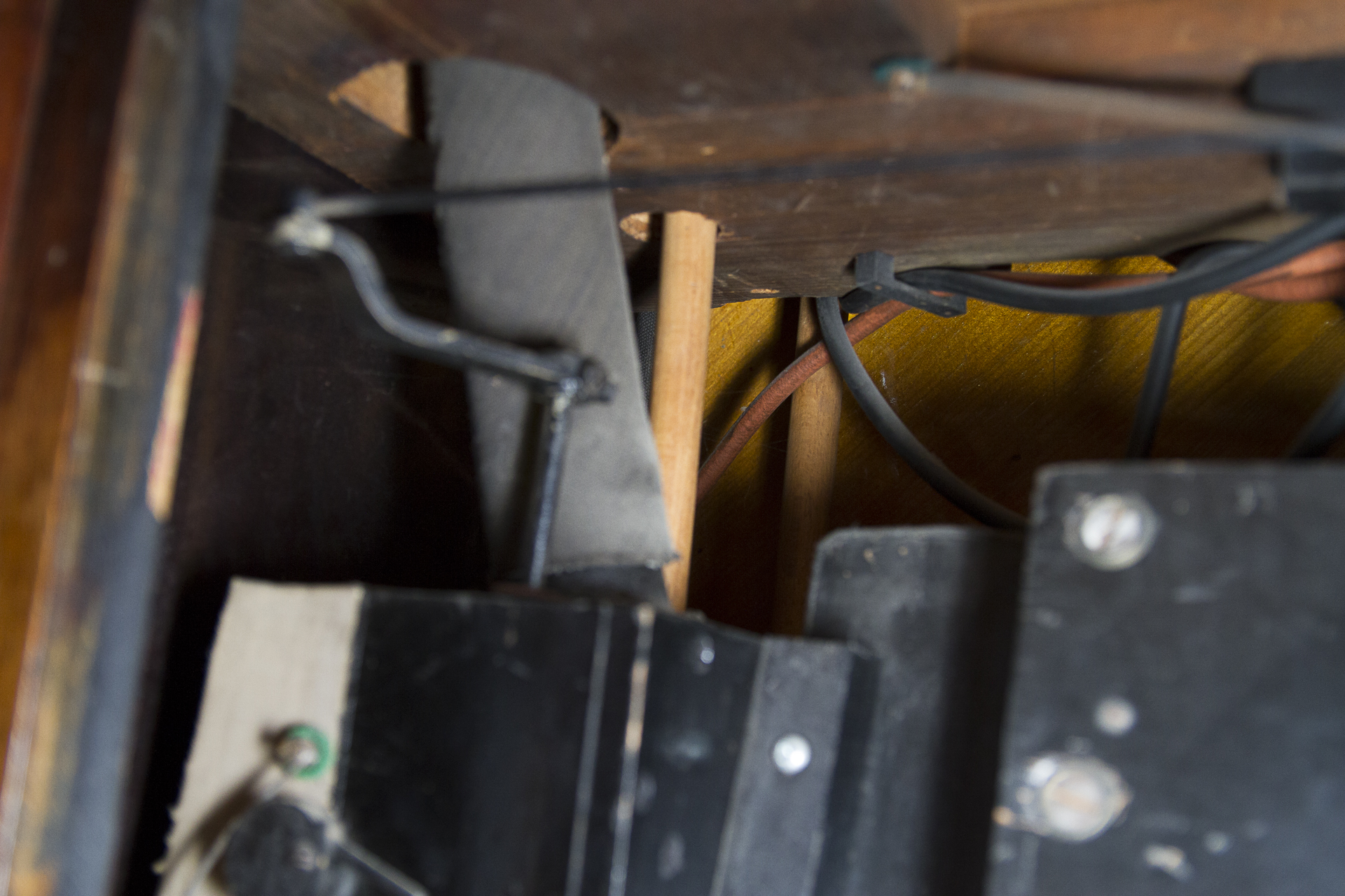
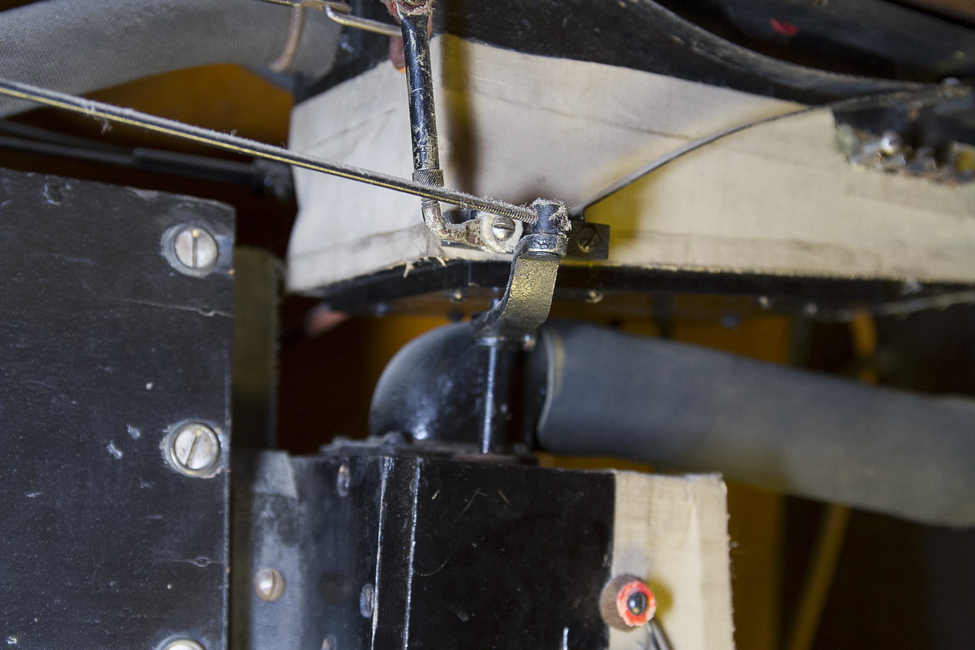
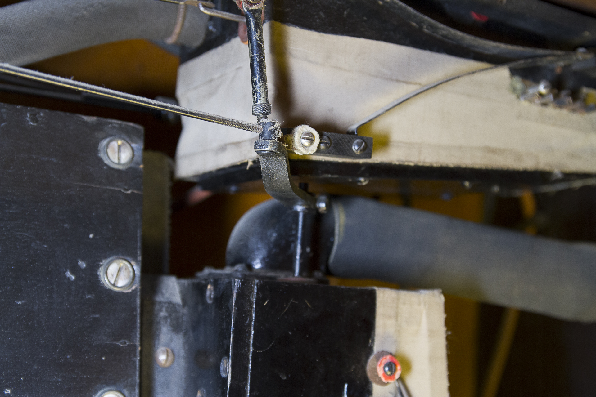
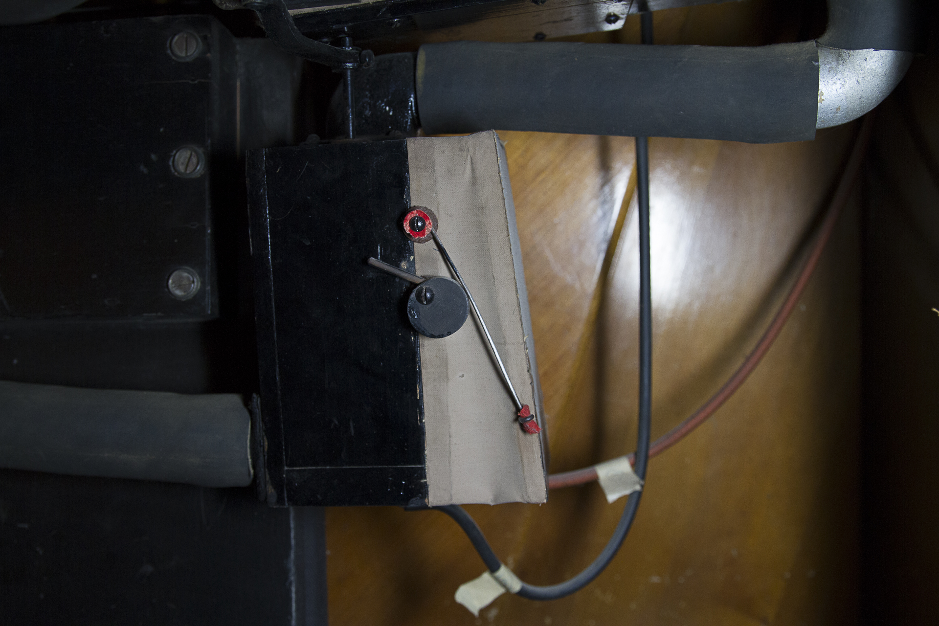
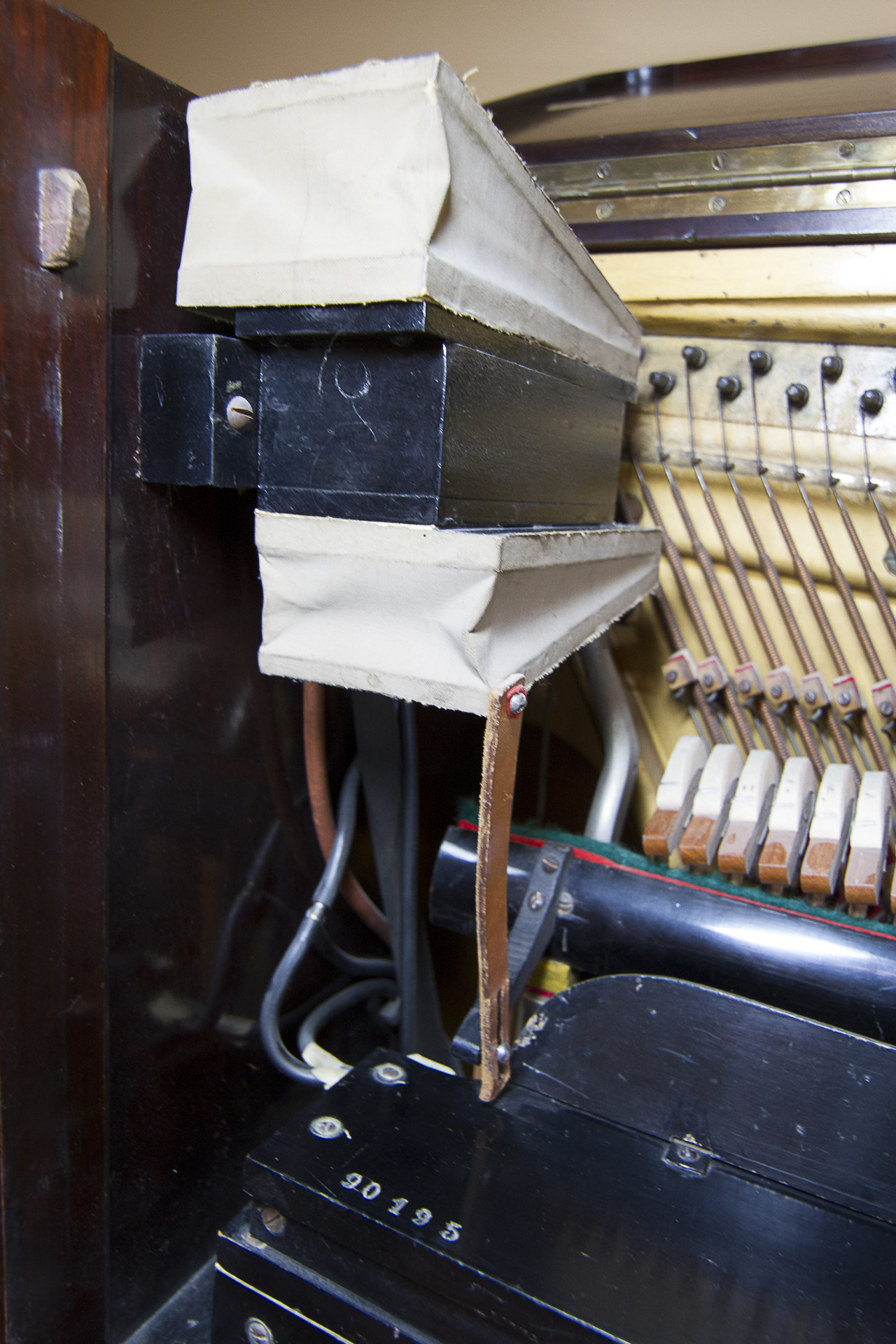
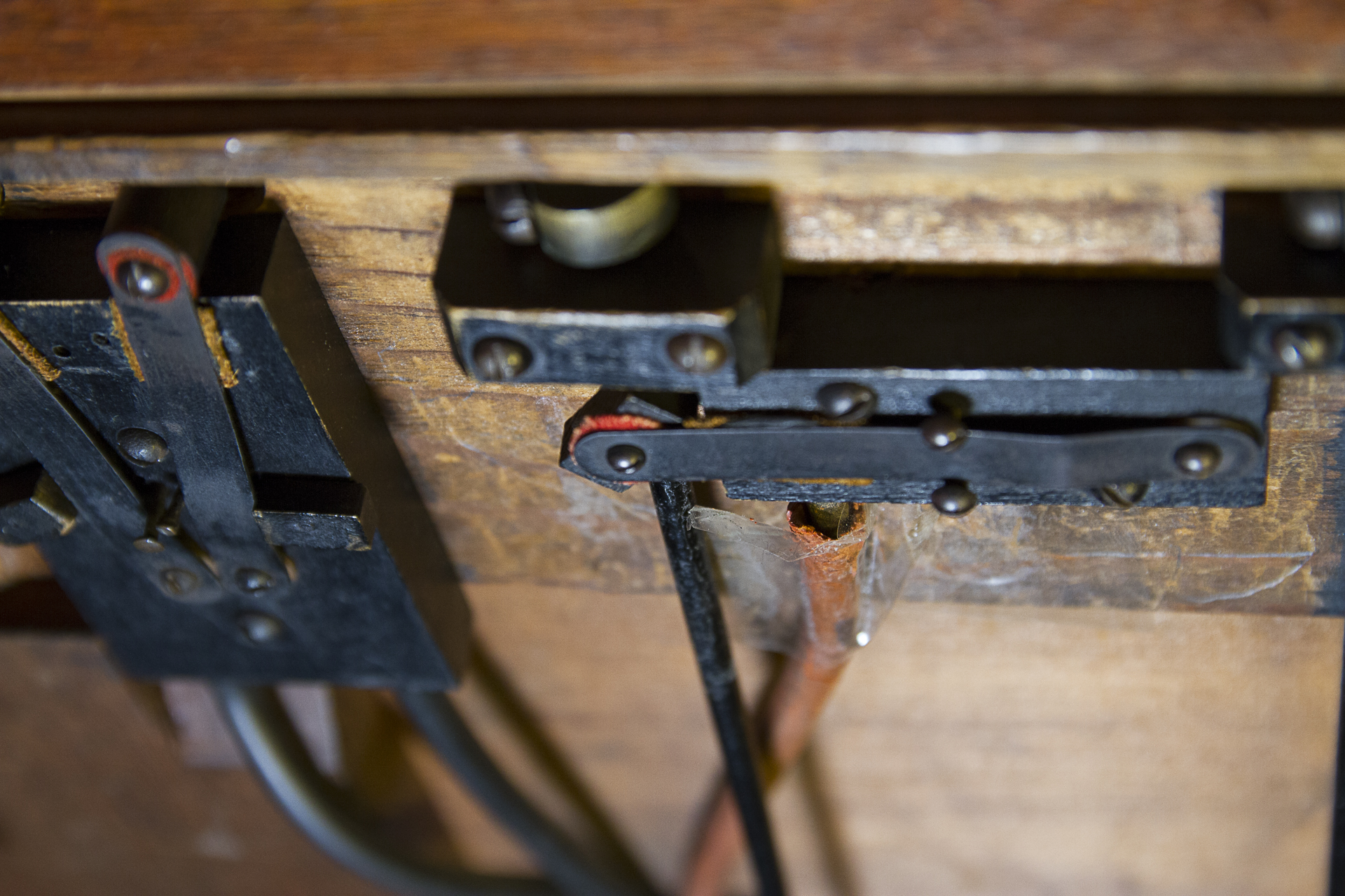
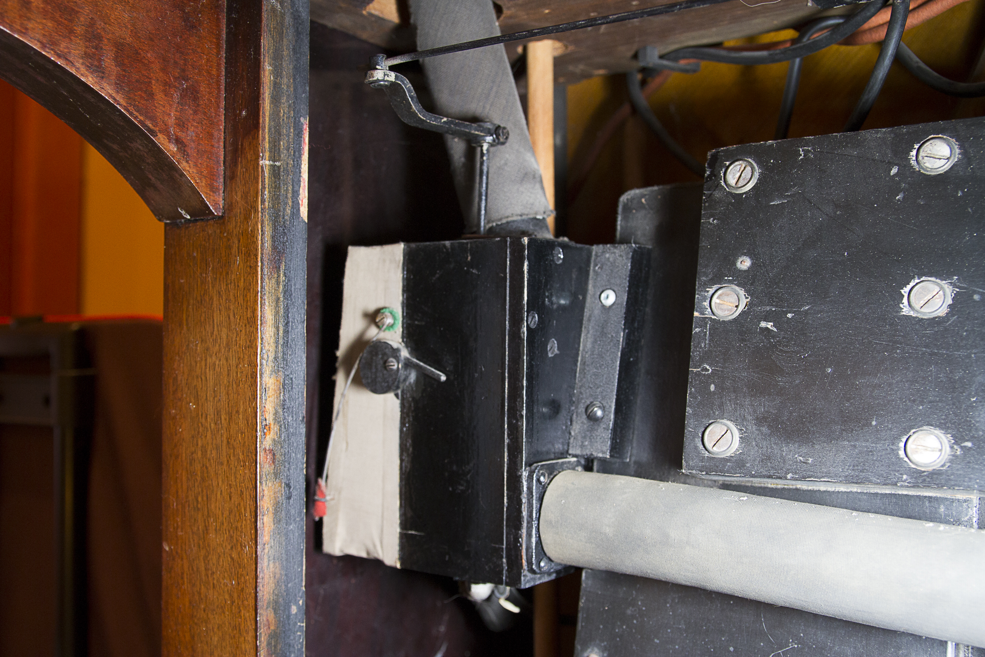
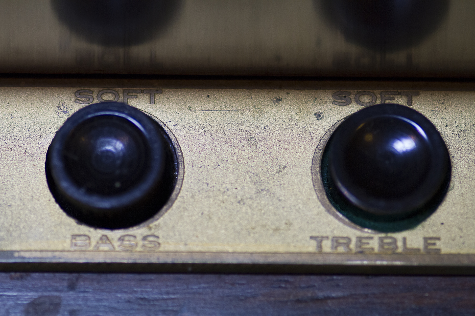
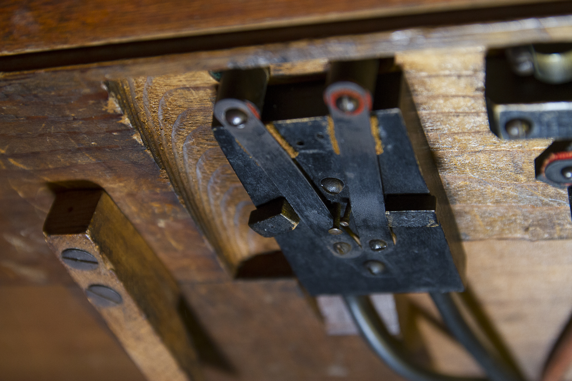
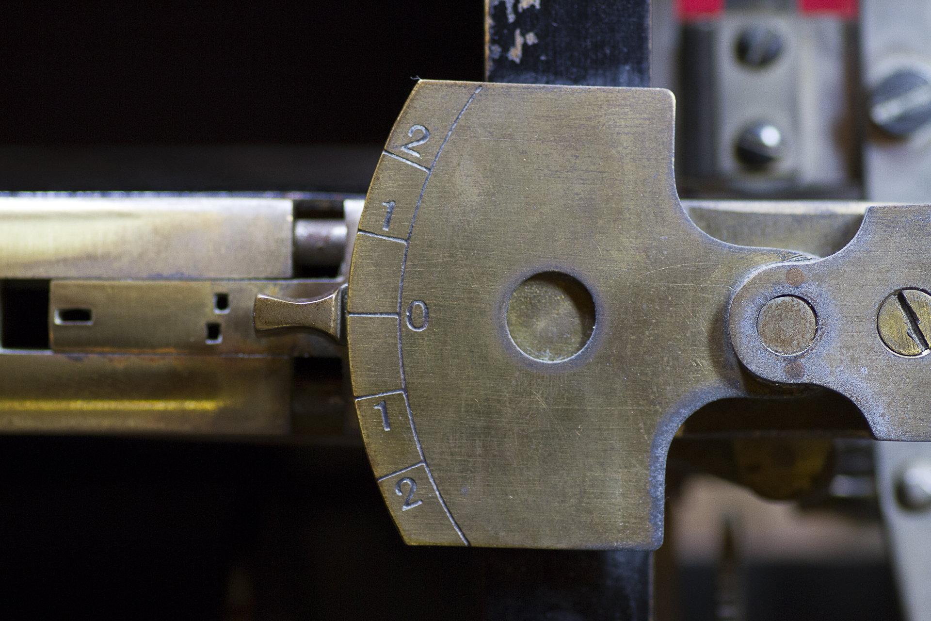
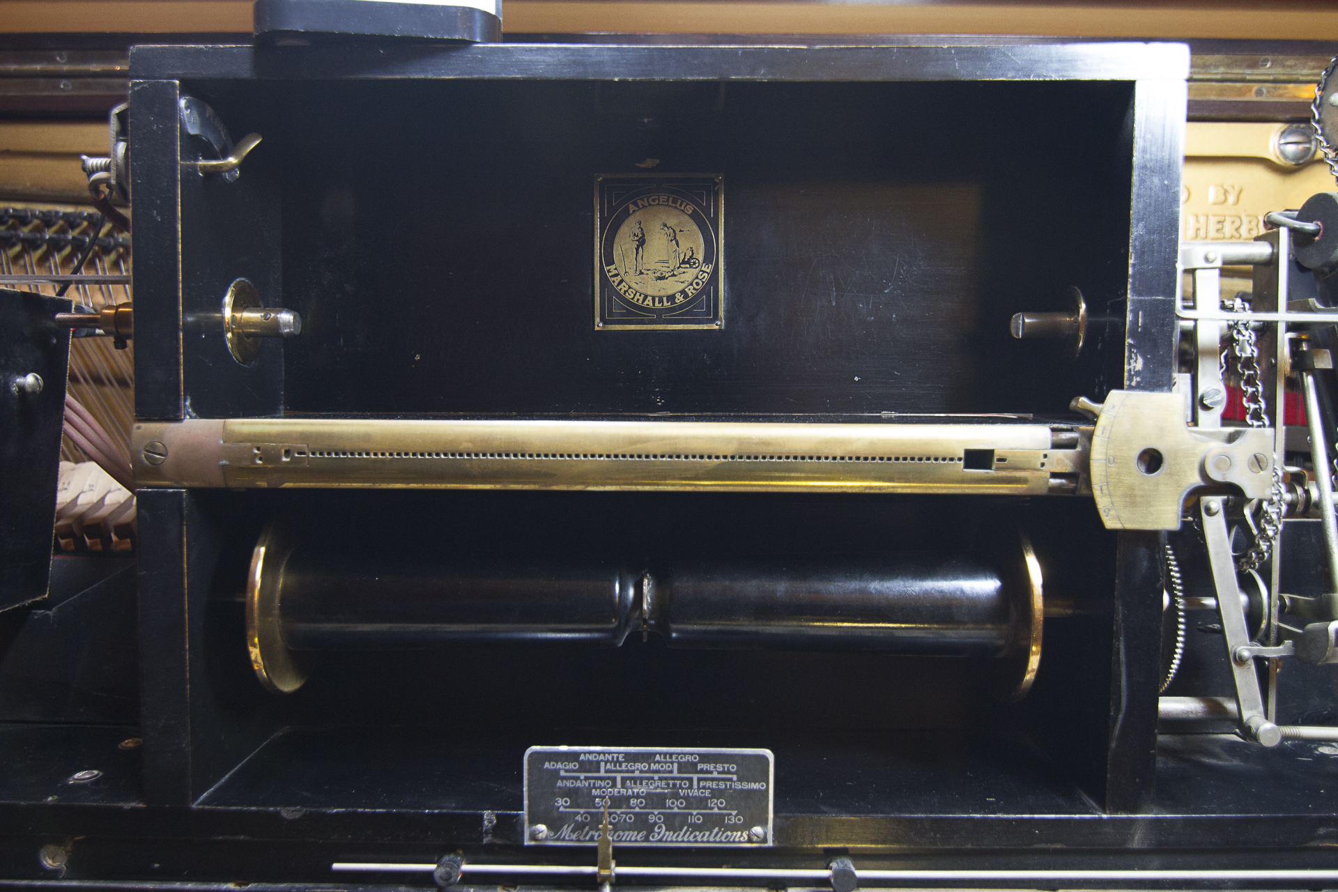
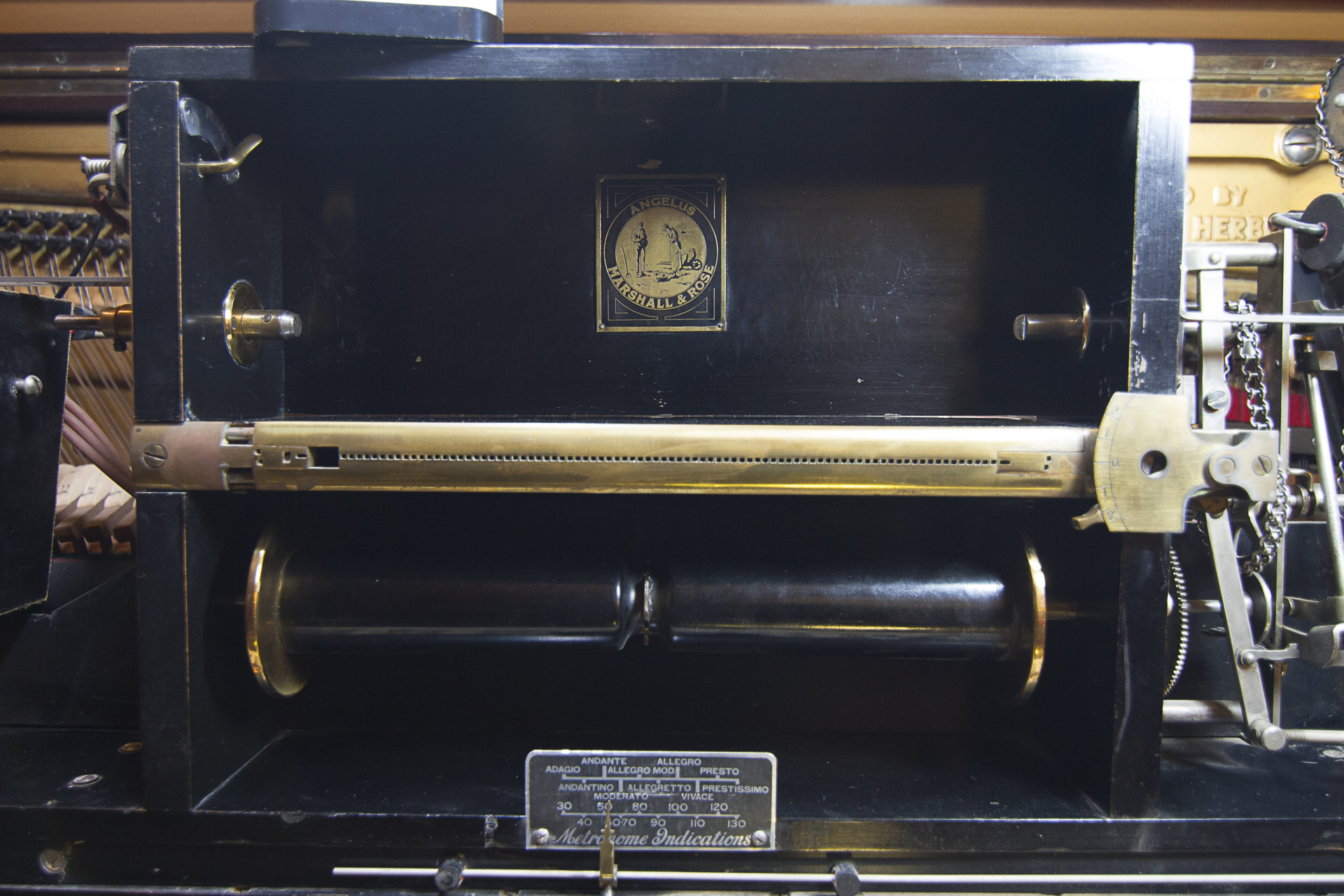
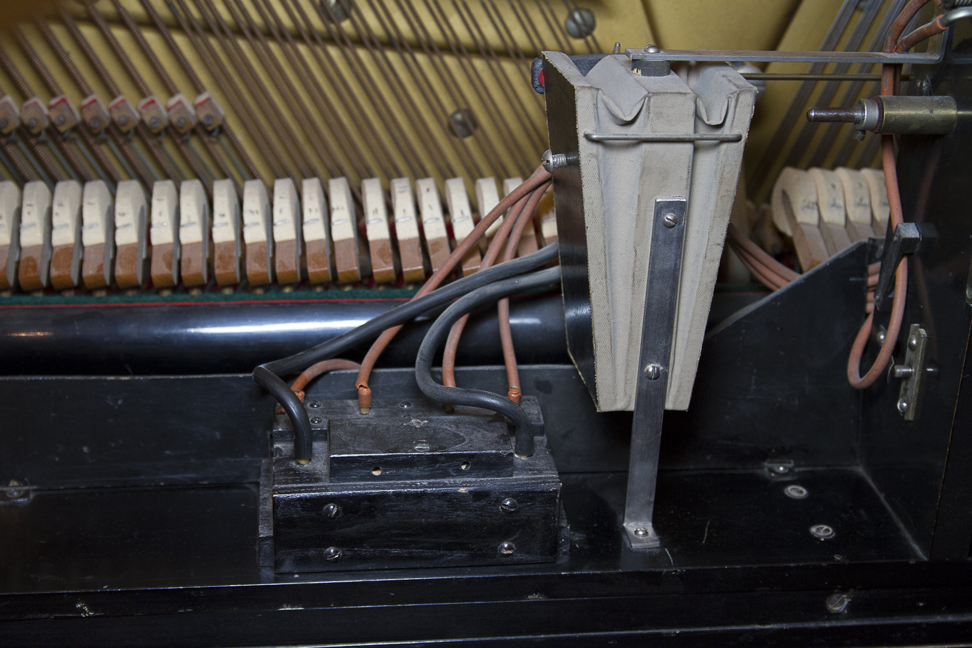
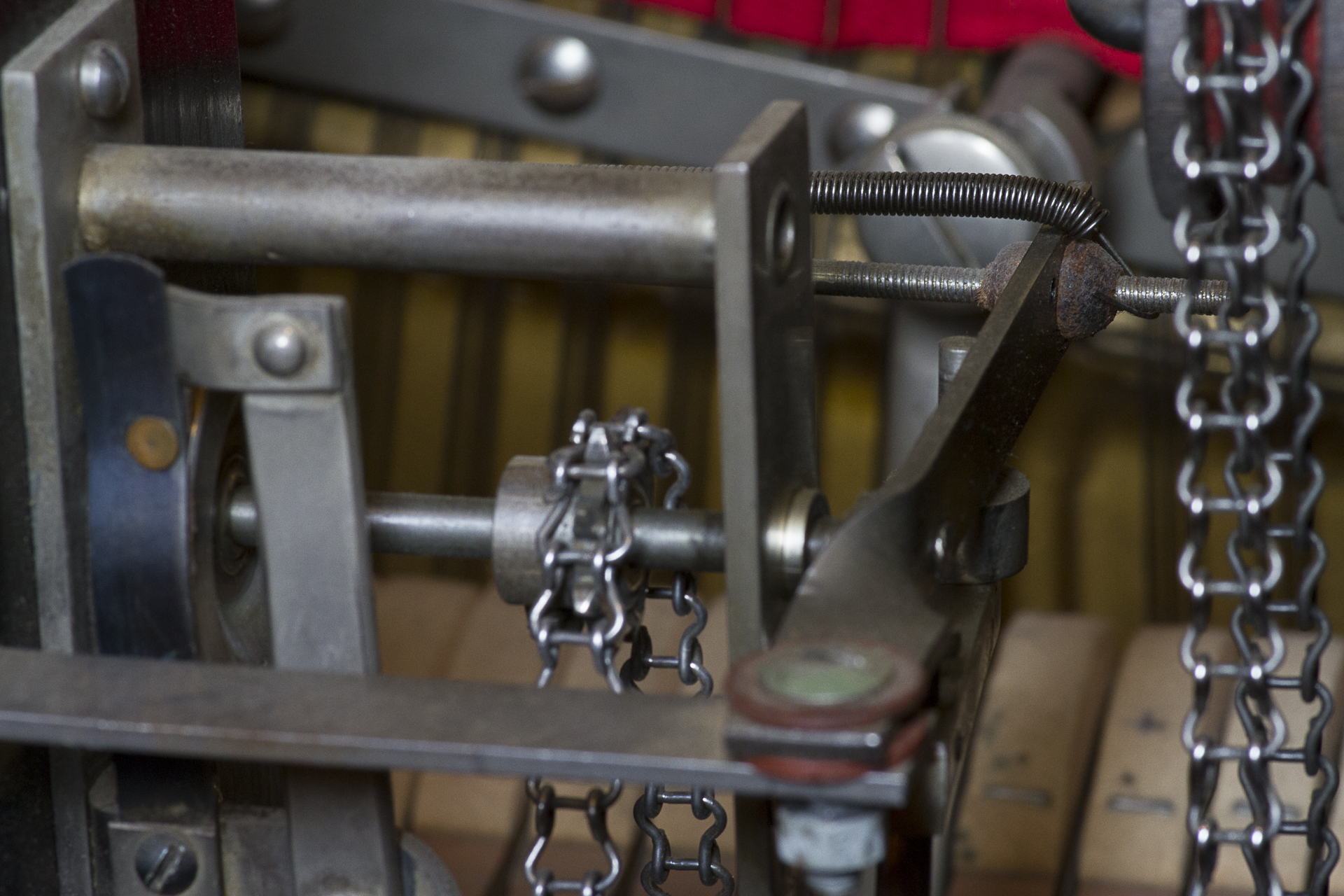
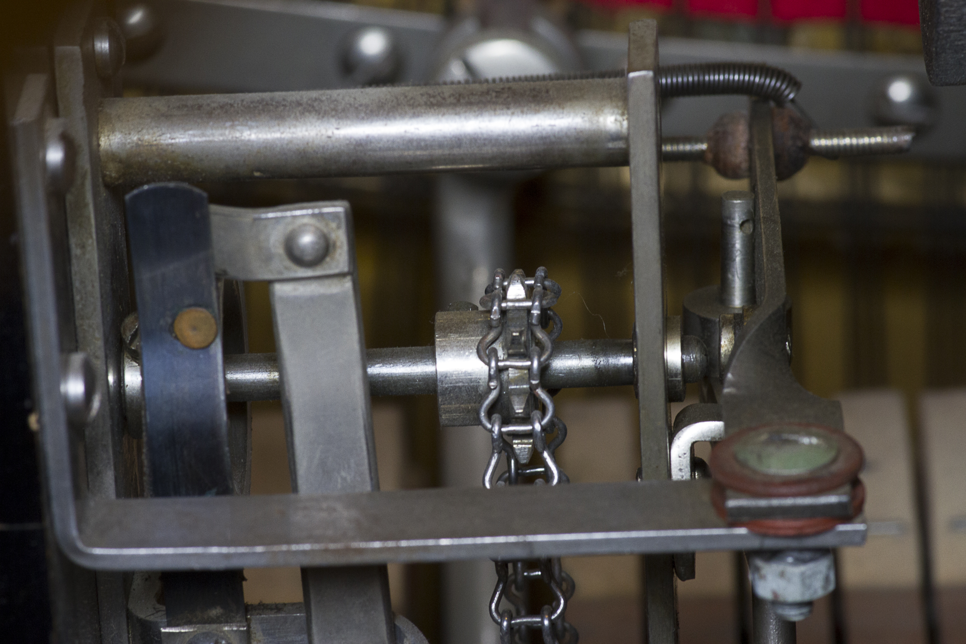
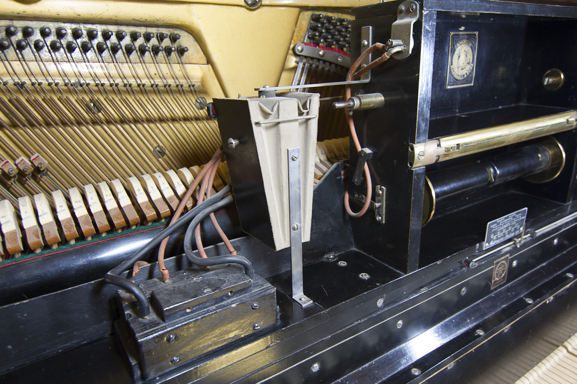
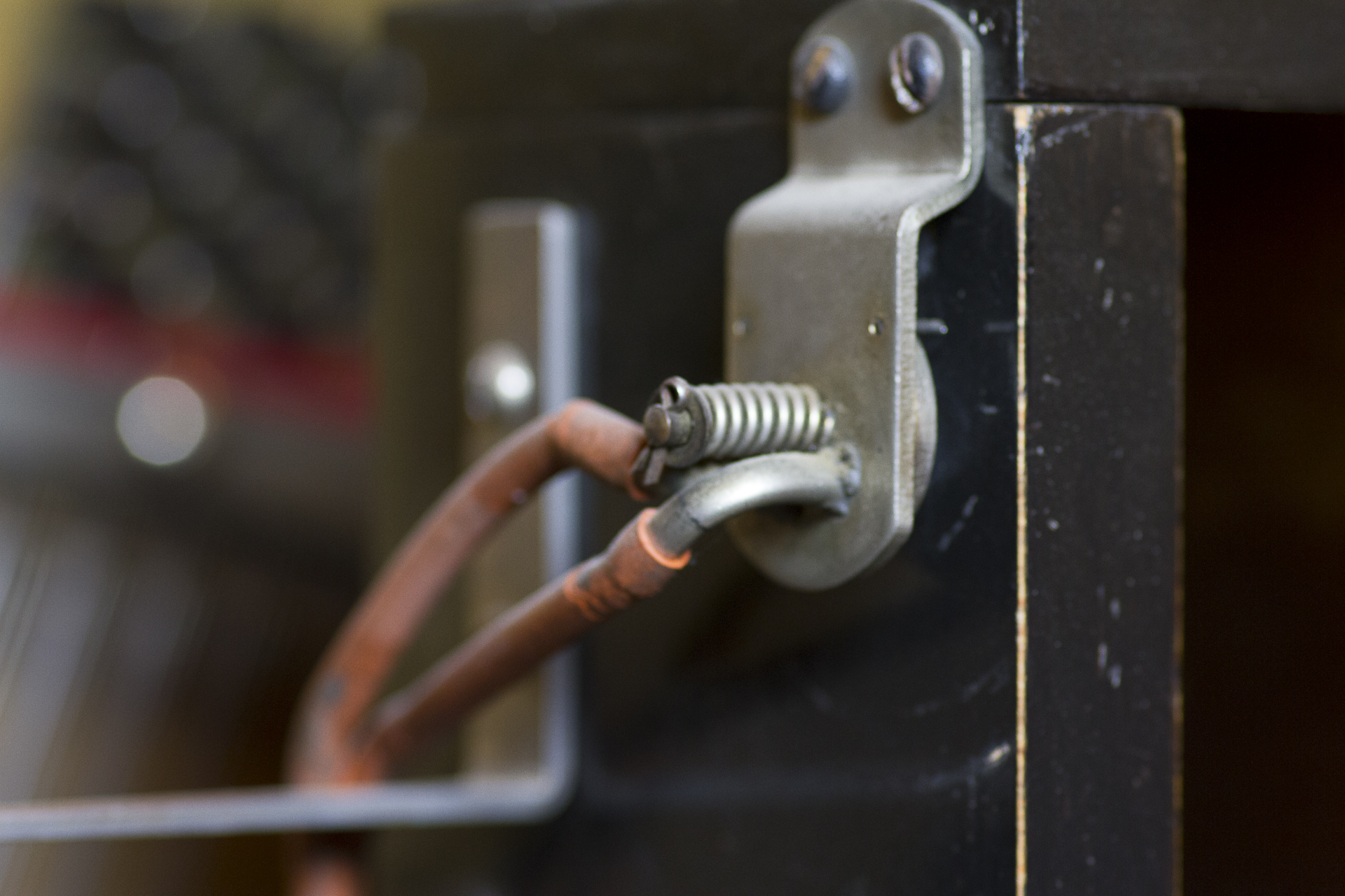
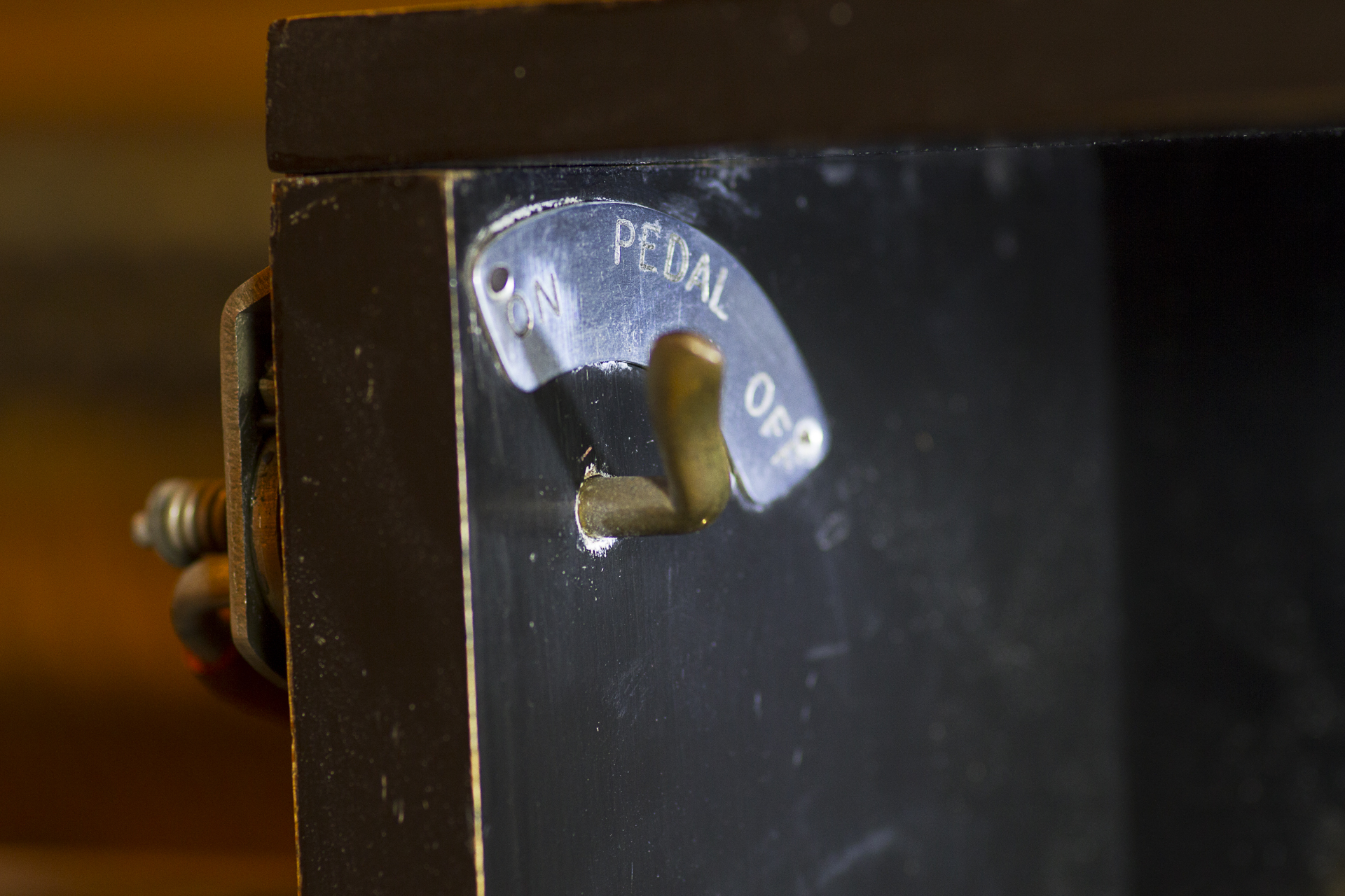
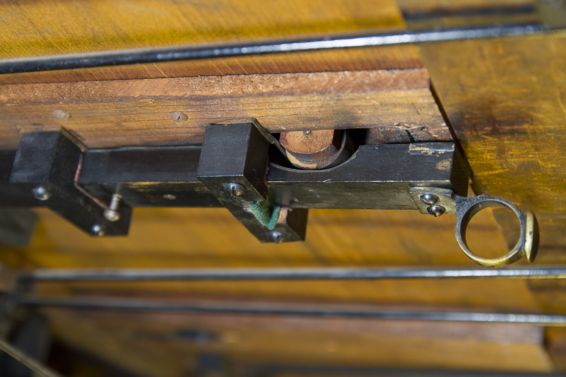
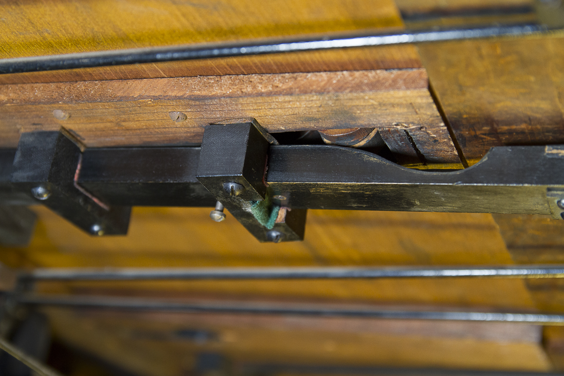
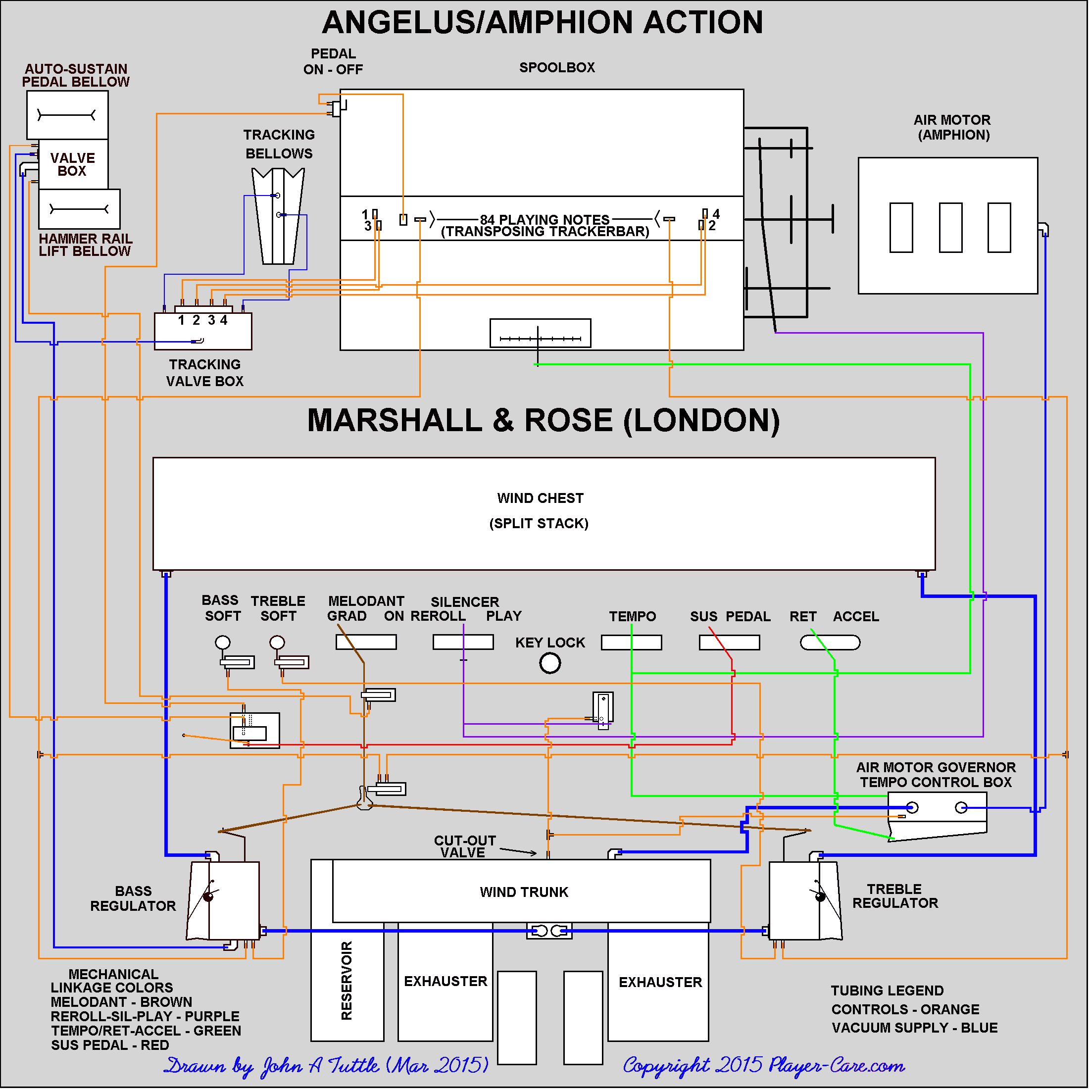
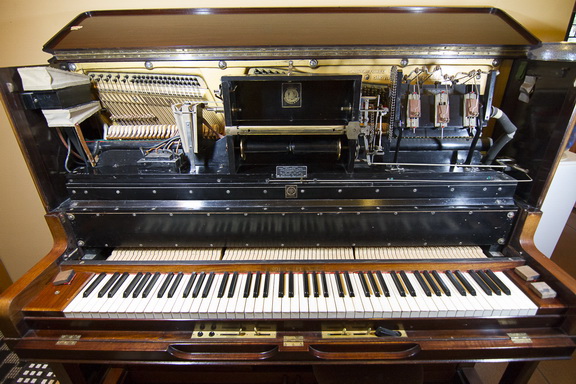
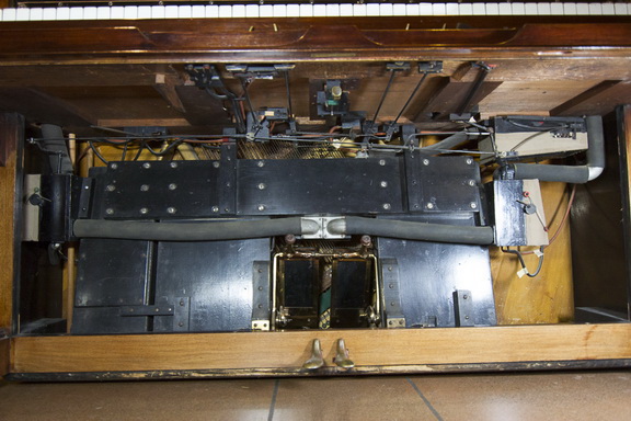
At this point, there are a few things that I know for certain.

1. The unit has what's called a 'split stack'. What this means is that the part of the system that senses the note perforations on the music roll is divided into the bass side and the treble side. Most likely there are an equal number of playing notes on each side.

2. The vacuum that is used to power each side of the stack is controlled by an independent vacuum regulator device which is placed between the exhauster assembly (which creates the vacuum by means of the foot pumps) and each side of the stack.

3. These two regulators also appear to contain a cut-off valve which cuts off the vacuum to the stack during the rewind cycle. (I will address more of the particulars of the regulators at a later time.)

4. The action of the cut-off valves is controlled by the movement of the Play/Rewind lever, but I can't quite make out which of the wooden air switches under the keybed are involved.

5. The action of the vacuum regulators is controlled in at least two different manners. One, which is obvious, involves the oversize rectangular holes in the trackerbar. These are typically called 'accent' or 'theme' holes and they operate the regulators automatically as the music is playing by means of turning a valve inside of the regulator 'on' and 'off' at the appropriate time.

NOTE: What I cannot see in any of the pictures are the points where the control hoses that operate the stack cut-out valves and the accent valves are connected to the regulators. I'm assuming they are on the back side of the regulators.

6. I'm relatively certain that the action of the regulators can also be controlled manually, but here again I can't see exactly how that is accomplished. There appears to be some linkage that's connected to a wooden valve where there are at least four control hoses.

NOTE: What I also need to know is the labeling on all of the controls in front of the keys. I'm almost certain that the pushbuttons are labeled Bass and Treble (left to right). But I'm uncertain about the two levers to the right of the pushbuttons. I'm also rather certain that levers to the right of the center of the piano are labeled Tempo and Play/Rewind (left to right), and the 'rocking' black control (far right) is probably labeled 'Ratard/Accelerando' (or some other trade name). What I cannot see clearly in the pictures is how that control interacts with the system. I get the feeling that it might be a secondary Tempo control, which would allow the user to accelerate or retard the tempo without changing the initial tempo setting as established by the Tempo control lever. If the rocking lever does effect the tempo, it does so mechanically, not pneumatically.

A few other obvious characteristics of the system:

It has a four-hole tracking device for keeping the holes in the roll aligned with the holes in the trackerbar. This is relatively common.

It has an automatic sustain device which is triggered by the square hole on the left side of the trackerbar between the two offset tracking holes and the rectangular theme (or accent) hole. Also, there will be a hose from the auto-sustain hole in the trackerbar that's connected to one side of the metal switch that's mounted in the upper half of the spoolbox on the left side wall. That switch is probably labeled 'Loud' or 'Sustain'. It is an 'On/Off' switch and the other hose that's connected to the switch will go to the valve on the auto-sustain device -which the the larger of the two bellows mounted on the left side wall of the piano in the upper half of the piano.

The bellows underneath the sustain bellows is the Bass Soft bellow. The Treble Soft bellows is located in the same position on the right side wall. These bellows are most likely triggered into operation manually by the two pushbuttons in front of the keys.

The air motor governor/tempo control box is highly sophisticated as evidenced by what appears to be eight or nine adjusters that are used for calibrating the linearity of the device. It also employs a rather unique way of adjusting the governor spring tension -which is used to automatically compensate for the changing vacuum levels within the system as the user pumps the pedals faster or slower to change the expression of the music. (This is a whole other topic.)

The pumper assembly (or Exhauster Assembly) is quite generic, having two large exhauster bellows and one smaller reservoir bellows (that stores the vacuum created by the exhausters).

The air motor, as I stated previously, was made by Amphion. Their 6-chamber motor is well known for both its power and its smoothness. Unlike the common 5-chamber motor, which has a 72 degree duty cycle, the 6-chamber motor has a 60 degree duty cycle.

The unit is equipped with a "transposing trackerbar", which allows the user to change the key of the music two notes either side of normal or 'zero'. However, I can't make out from the pictures exactly how the user is suppose to move the position of the adjuster. (That's the fairly large brass piece with the markings on the front that's located at the right end of the trackerbar.) It's also important to note that anytime you have a transposing trackerbar, you also have rubber tubing connected to the trackerbar which flexes as the bar is move right or left of center. Most often, this tubing has become brittle and cracked, or it will be so hard that the bar cannot be moved.

The transmission is fairly straightforward, having both forward roll and rewind brakes. It's a little difficult to tell (from the pictures) how the rewind brake gets engaged by the movement of the Play/Rewind lever... Also, I can't see how either of the brakes would be adjusted for the proper tension without bending metal pieces. (Normally there would be some relatively easy way to adjust the brake tension.)

I think that about covers the basics. What I need are closeup pictures of all of the components that are mounted under the keybed. These should be taken at about one to two feet from the subject and each subject should be shot from two different angles. You should start at either the left or right end and shot the pictures progressively from one side to the other. Imagine, if you will, that I'm sticking my head inside the piano and looking closely to determine how each of the components is connected to another component. So, if a piece of linkage or a rubber tube goes from point A to piano B, I have to be able to see that in a series of pictures. Eventually, I'll draw a diagram, or a sort of roadmap, of what each of the levers or buttons control.

Lastly, it should go without saying that most, if not all of this data will be used in the creation of a treatise about the player action.

========================================

After Receiving Better Pictures

The picture below shows all of the mechanical linkage under the keybed.
The details of each control and the parts with which they interact will be explained
to some extent in the 16 individual segments that follow.

Each picture is numbered in order left to right by rows.

=====================================================================

    Marshall And Rose Player #1

    The buttons and levers at the front of the key bed are as follows, in order from left to right.

    Bass Soft and Treble Soft buttons, Melodant (Grad - On) lever, Reroll - Silencer - Play lever, Tempo lever, Sus - pedal lever, Rit - Accel toggle.

    Starting at the right we have the Rit - Accel lever. Photo 1 & 2

    Push the Rit lever down, raises and lowers the bellows on the lower right side, photo 3 & 4.

=====================================================================

    Marshall And Rose Player #2

    Sus Pedal lever Photo 5

    Below the keyboard Photos 6 & 7 , switching back and forth between the two photos you see the action of the lever.

=====================================================================

    Marshall And Rose Player #3

    Sustain Pedal lever (part two).

    The lever moves a wooden switch photos 8 & 9. Switching back and forth between these photos you can see the movement of the switch.

    Two vacuum lines are operated from this switch. One on the fixed part of the switch goes to the left side of the stacker photo 10 line #4.

    The second vacuum line on the moving part of the switch goes to a "T" section, from there to the upper bellows on the left side of the piano, and also to line 15 to the stack. Photo 10 & 10a.

=====================================================================

    Marshall And Rose Player #4 (Tempo Control Part 1)

    Tempo lever photo 11

    The action of the Tempo lever is viewed by toggling photos 11 & 12 as well as photos 13 & 14.

    Note the armature behind the front armature. It goes to linkage which controls the movement of the Metronome Indicator in the spoolbox. (see Marshall And Rose Player #5 below)

=====================================================================

    Marshall And Rose Player #5 (Tempo Control Part 2)

    The Tempo lever has two moving arms under the keyboard bed. The rear arm has a mechanical link, photo 16, front arm in this picture, to the Metronome Indicator Pointer photo 17.

    The front arm, under the keyboard bed, is linked to the tempo slider valve inside the tempo control box/air motor governor, which is mounted on the underside of the keybed (right side), photos 18 & 19, toggle them back and forth.

=====================================================================

    Marshall And Rose Player #6

    Silencer - Reroll - Play photo 20.

    This lever action toggle photos 21 & 22. Has two moving arms, the rear arm has a mechanical link photo 23 the rear arm in this photo.

    Moves in front of the air motor left to right and connected to the transmission.

=====================================================================

    Marshall And Rose Player #7

    Silence - Reroll - Play continued.

    At the transmission toggle photos 24 & 25 as well as photos 26 & 27 to see the action of this lever

    I suspect it may be a brake or a drag for the paper roll?

=====================================================================

    Marshall And Rose Player #8

    Silence - Reroll - Play (continued).

    The front arm of the lever action connects to a wooden switch photos 21 &22 see previous email and toggle these photos back and forth.

    This switch has a vacuum line that goes to a " T " photo 28, one part goes to the top of the pump chamber just out of site in this photo.

    The other part of the " T " goes to the back side of the upper bellows, photo 29, on bottom right as seen in the photo.

=====================================================================

    Marshall And Rose Player #9

    Melodant - Grad - On lever Photo 30.

    The action of this leave can be seen by toggling photos 31 & 32 back and forth.

    There is a wooden switch associated with its movement when the lever is to the right in the on position it activates the switch with two vacuum lines attached.

=====================================================================

    Marshall And Rose Player #10

    Melodant - Grad - On lever continued.

    The two vacuum lines one goes to the bottom of the right lower bellows, photo 37, the other one goes to upper left bellows, photo 38.

    The levers mechanical linkage goes to lower left bellows , photos 33 & 34. Toggle them back and forth to see the action, and to the lower right upper bellows photos 35 & 36, toggle to see the action.

=====================================================================

    Marshall And Rose Player #11

    Melodant - Grad - On lever continued.

    This lever has a second switch , photo 39, it also has a vacuum line to it.

    This vacuum line goes to the lower left bellows, photo 40.

=====================================================================

    Marshall And Rose Player #12

    Bass and Treble buttons. Photo 41.

    Pressing a button activates a mechanical switch. Photo 42.

    Press the left Bass button, the vacuum line goes to the bottom of the lower left bellows. Photo 43.

    Press the right Treble button, The vacuum line goes to the bottom of the lower right bellows. Photo 44

=====================================================================

    Marshall And Rose Player #13

    Spool Box.

    Photo 45, Mechanical adjustment of the tracker bar.

    Photo 46, Up two positions.

    Photo 47, Down two positions

=====================================================================

    Marshall And Rose Player #14

    Left of the spool box, photo 48, has a bellows & vacuum lines with a valve box.

    The vacuum lines go to the rear of the spool box, may be in connection with the square holes of the tracker bar?

    At the back of the bellows in photo 48 is a rod which can move left and right and goes to the transmission as seen back right in photos 49 & 50 with the leather nuts.

=====================================================================

    Marshall And Rose Player #15

    Left side of spool box photo 51. Has a mechanical switch photo 52. And is seen on the inside of spool box photo 53.

=====================================================================

    Marshall And Rose Player #16

    Manual ON/OFF 'Key Lock' device

    Photos 54 & 55 show a finger pull that causes a roller to rise and fall under the keyboard. Toggle these photos to see the action.

That's some mess you've got there....

I think the only way we can find out where the vacuum comes from for the automatic tracking device is the unscrew the valve box from the deck board and look underneath the box.

Regarding the Pedal On-Off switch, what we'll need to find out next is where that lead pipe goes.

As for tubing, I have 7/32" ID tubing, which is the standard OD of lead tubing in player pianos. I also have both thin wall and regular wall trackerbar tubing. However, the question is: Do you really want to make up all of those reducing connections? If I were doing the job, I'd remove all of the lead tubing and then replace it all with regular trackerbar (TB) tubing. I have videos about removing the lead tubing and replacing it with TB tubing.

I noticed the two pieces of folded tubing right off the bat. I think they were originally connected to the two theme holes (rectangular holes) in the bar. I can't imagine the manufacturer running tubing to the trackerbar for no reason...

At some point, I feel we're going to have to fall back to looking at the tubing from the standpoint of common player piano logic. All of the devices in a player piano require 'on-off' signals (or binary logic) if a valve is involved. Other devices, like the tempo control box, air motor governor, and (in this case) the bass and treble regulators have mechanical linkage that is used to move a knife valve or a sliding valve to effect a change in the flow of vacuum.

Player Piano Reference Materials - Click Here

We Gladly Accept These Cards
Discover, VISA, MasterCard

back to top..To The Top of this Page . . . . . . . . . . . back to index ..To The HOME Page


This page was last revised September 27, 2019 by John A. Tuttle, who Assumes No Liability
For The Accuracy or Validity of the Statements and/or Opinions
Expressed within the Pages of the Player-Care Domain.
Cartoon Graphics by E7 Style Graphics (Eric Styles)


Since "Player-Care" is an internet business, I prefer that we correspond via E-Mail (click here to fill out the 'Request Form'). However, if I'm not in the middle of some other activity, you can reach me at 732-840-8787. But please understand that during the hours from 8AM-5PM EST (Mon-Sat), I'm generally quite busy. So, I probably won't answer the phone. If you get the answering machine, please leave a detailed message stating the reason for your call. Also, repeat your name and phone number clearly and distinctly. By necessity, I prioritize everything in my life. And, if you call and just leave your name and number, and ask me to call you back, it might be a day or two before I return your call. Why? Because I don't know why you want me to call and I might not be prepared to assist you in an effective and efficient manner. If you leave me an E-Mail address (which I prefer), spell it out phonetically. The more you do to help me, the more I can help you in return. Don't rush. You have four minutes to record your message.


Grand 16 IconGrand 32 Icon

407 19th Ave, Brick, NJ, 08724
Phone Number 732-840-8787
(Voicemail Only, No Texts)
Upright 32 IconUpright 16 Icon

Google Adsense Ad