
|

|

|
|
|
|
|
| Home | Manuals | Supplies | Search | Consult | Contact | Testing | Service |
|
In an effort to figure out exactly what the engineers at Ampico were thinking when they created the function switches, I've examined dozens of original and after-market switches. While it's obvious that some relatively minor changes were made to the molds that Ampico created, determining why they made those changes is quite difficult. Fortunately, the basic angles, thicknesses, spacings, and hole sizes remained fairly consistent.
What's obvious to those who do CNC machining (as opposed to those who make molds) is that the cost goes up every time a different tool is required in the cutting process.
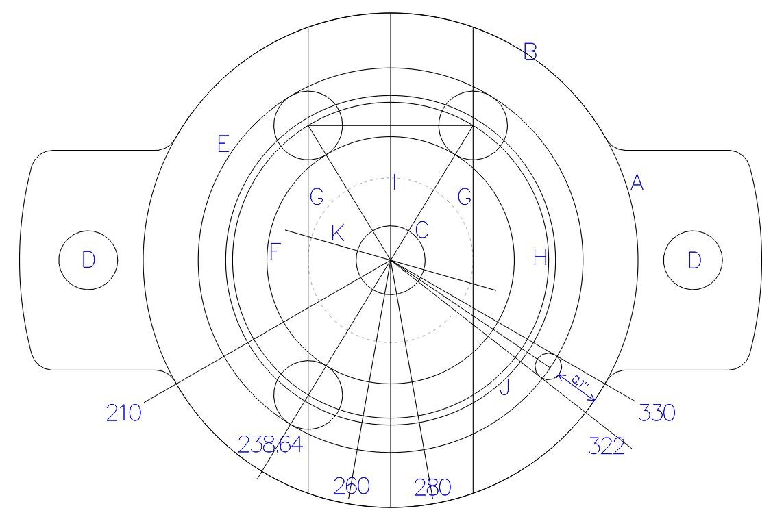
Ampico 'A' Function Switch Specifications
Order of events when creating the CAD file NOTE: Letters in brackets [] denote specific locations in drawing.
Diameter of face on base -create circle: 1-1/8" [B] https://youtu.be/VD41saIe_gY |
| Player Piano Reference Materials - Click Here |

![]() ..To
The Top of this Page . . . . . . . . . . .
..To
The Top of this Page . . . . . . . . . . . ![]() ..To The HOME Page
..To The HOME Page
|
Since "Player-Care" is an internet business, I prefer that we correspond via E-Mail (click here to fill out the 'Request Form'). However, if I'm not in the middle of some other activity, you can reach me at 732-840-8787. But please understand that during the hours from 8AM-5PM EST (Mon-Sat), I'm generally quite busy. So, I probably won't answer the phone. If you get the answering machine, please leave a detailed message stating the reason for your call. Also, repeat your name and phone number clearly and distinctly. By necessity, I prioritize everything in my life. And, if you call and just leave your name and number, and ask me to call you back, it might be a day or two before I return your call. Why? Because I don't know why you want me to call and I might not be prepared to assist you in an effective and efficient manner. If you leave me an E-Mail address (which I prefer), spell it out phonetically. The more you do to help me, the more I can help you in return. Don't rush. You have four minutes to record your message. |
|
407 19th Ave, Brick, NJ, 08724 Phone Number 732-840-8787 (Voicemail Only, No Texts) |
