
|

|

|
|
|
|
|
| Home | Manuals | Supplies | Search | Consult | Contact | Testing | Service |


|
|
As any bellows in the motor completes its power stroke, vacuum to the bellows should be cut off by the position of the sliding valve. To give you a better perspective, let's start with the attached graphic and work through the four steps of one complete cycle of rotation. NOTE, the positions of the sliding valves in this graphic do not represent the best position for every air motor. They're all a little different. However, the basic operating principles of a correctly timed air motor are the same.
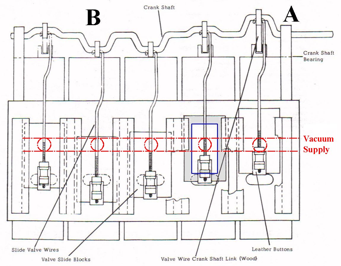
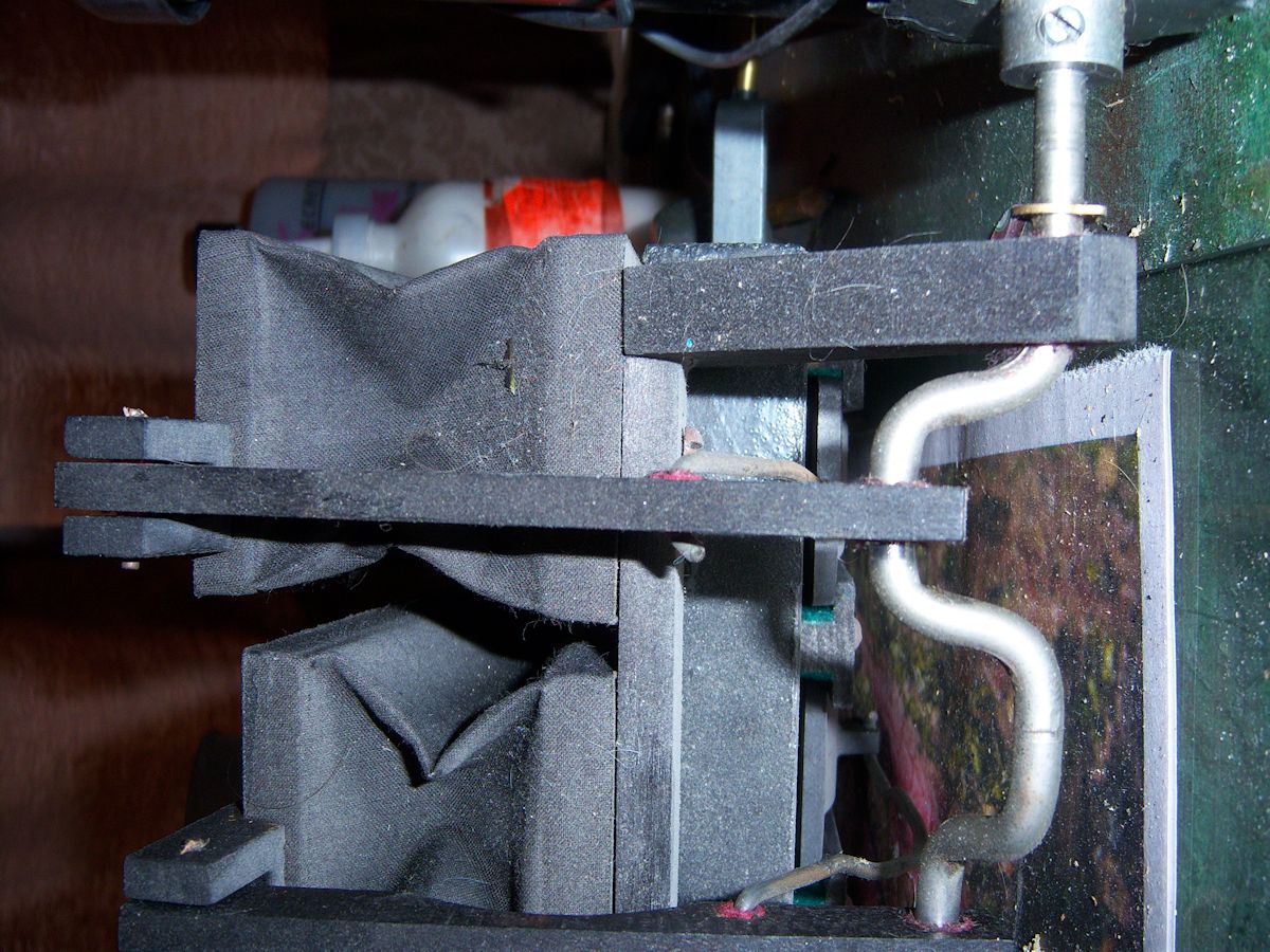
At point 'A', the sliding valve is at its uppermost position and there is no vacuum in the bellow. At the same time (although the graphic doesn't accurately represent the exact angle of the lobe on the crankshaft) the sliding valve at point 'B' is near the lowermost position and vacuum is being applied to the bellow. And since vacuum is being applied to that bellows, the crankshaft will rotate in a clockwise direction. I only state this so we have a point of reference with regards to the direction of rotation. As lobe 'A' rotates clockwise 90 degrees from its initial (or uppermost) position, it will reach what's fairly commonly referred to as top-dead-center (TDC), and at that point the bellows will be open to its maximum. That is not to say that the bellows will be "fully" open. In fact, if the bellows is fully open when the crankshaft reaches TDC, the span of the bellows is too small. (The picture 'open-at-TDC' shows what the bellows should look like when the lobe for that bellows reaches TDC.)
 And, if that's the case, the motor will lope as it strains to get beyond the increased friction of the cloth as the cloth gets increasingly tighter. BUT, we'll assume that the cloth is fine and the bellows is like it is in the picture. Referring back to the graphic, note the blue rectangle and the light gray shaded area. The gray shaded area represents the wooden frame of the sliding valve and the area inside of the blue box represents the area through with vacuum will pass from the vacuum supply (the red holes) to the bellows (the oblong holes). Now we begin to time the position of the sliding valves. The moment after the crankshaft passes TDC, the bottom edge of the blue rectangle should pass over the upper edge of the oblong opening. This will allow the vacuum to flow from the supply channel into the bellow. Since you cannot see when this happens (the holes are covered by the sliding valve), you need to apply vacuum to the motor. (This is best done by connecting a length of rubber hose to the vacuum supply fitting and sucking on the hose by mouth.) With vacuum applied, rotate the crankshaft by hand from just before TDC to just after TDC. As you do this, watch the bellows cloth closely, You will see that just as the inside edge of the slider crosses over the upper edge of the oblong hole leading to the bellows, the cloth will 'suck inwards'. If the cloth starts sucking inwards before the crankshaft reaches TDC, you need to adjust the position of the sliding valve upwards. If the cloth starts sucking in too long after the crankshaft passes TDC, the motor will have less power, and the sliding valve should be adjusted downwards. Normally, once you've finished adjusting one sliding valve correctly, you can adjust all of the others to match the ones that's been properly adjusted. This is most easily accomplished by looking at the space between the bottom of the adjusted sliding valve and the top edge of its associated oblong hole. Generally speaking, that distance is about 1/8", but it does vary depending on the manufacturer. Some are as little as 1/32". |

![]() ..To
The Top of this Page . . . . . . . . . . .
..To
The Top of this Page . . . . . . . . . . . ![]() ..To The HOME Page
..To The HOME Page
|
Since "Player-Care" is an internet business, I prefer that we correspond via E-Mail (click here to fill out the 'Request Form'). However, if I'm not in the middle of some other activity, you can reach me at 732-840-8787. But please understand that during the hours from 8AM-5PM EST (Mon-Sat), I'm generally quite busy. So, I probably won't answer the phone. If you get the answering machine, please leave a detailed message stating the reason for your call. Also, repeat your name and phone number clearly and distinctly. By necessity, I prioritize everything in my life. And, if you call and just leave your name and number, and ask me to call you back, it might be a day or two before I return your call. Why? Because I don't know why you want me to call and I might not be prepared to assist you in an effective and efficient manner. If you leave me an E-Mail address (which I prefer), spell it out phonetically. The more you do to help me, the more I can help you in return. Don't rush. You have four minutes to record your message. |
|
407 19th Ave, Brick, NJ, 08724 Phone Number 732-840-8787 (Voicemail Only, No Texts) |
