
|

|

|
|
|
|
|
| Home | Manuals | Supplies | Search | Consult | Contact | Testing | Service |


Adjusting the |
|
Restoring the Lauter-Humana Air Motor is not a simple task. So it only follows that adjusting it to work properly is also somewhat difficult. Unfortunately, the adjustment phase looks pretty easy. Consequently, many Lauter-Humana air motors are incorrectly regulated and therefore perform at 'less-than-optimum' for no apparent reason. Fortunately, with a little understanding of the basic "musts", even a 'less-than-perfectly' restored unit can be adjusted to work exceedingly well without starting over. |
|
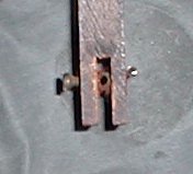
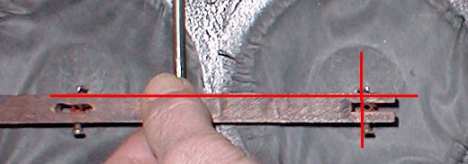
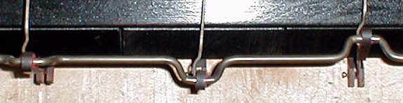
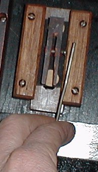
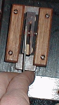
NOTE: As with any procedure, it is highly recommended that you read the entire treatise before tackling the job. In a few instances, it is not possible to address every aspect of a particular process within the same paragraph, as doing so might lead to confusion. Once the intentions of the various steps are understood, making the adjustments will go more smoothly. Begin the adjustment process by loosening all nine of the set screws that hold the pieces of linkage together. Then disconnect all of the pieces of linkage from their associated parts. Turn the motor so the pouches are facing upwards. Move the three rocking levers out of the way and examine the angle of the protruding pouch pins. All six pins "must" be pointing straight up and each set of opposing pins "must" be in a straight line. (See Fig 1-2) If they are not as just described, DO NOT start bending the pins.
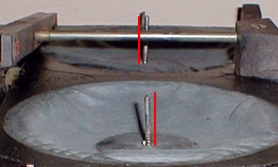  Figures 1 & 2 - Checking Pin Placement
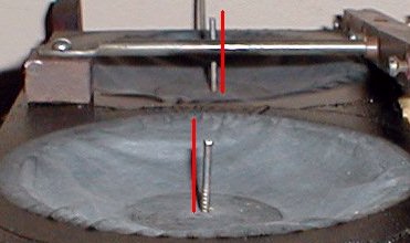
The next step is to move any of the three levers over its respective set of pouch pins. Ideally, the holes in the wire keepers will line up perfectly with the pouch pins. If they don't, the pins have to be bent accordingly. Unless you have a wire bending tool (See Fig 3), bending the wire can be a rather difficult task. However, the first, or primary bend should be made as close to the fiber disk as possible. Exercise caution as the head of the pin, which is actually a flat head nail, is hide glued between a piece of heavy bellows cloth and an 1/8" thick fiber disk, and fracturing the glue could create a small leak. (Should that happen, the base of the pin, where it comes through the cloth, can be sealed to the cloth with Phenoseal.) While making the primary bend, try to anticipate the second bend. Ideally, the combination of the two bends will render a 1/4" section of pin, at the top, that points straight up. As can be seen in the two pictures below (See Fig 4-5), the pouch pins are grossly out of position.
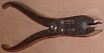 Figure 3 - Wire Bending Pliers
  Figures 4 & 5 - Location of Pins Before Bending Below is a picture of a pin after the first bend has been made. (See Fig 6) Note the relative position of the set screw to the pin. As explained previously, anticipating the second bend will help avoid bending the pin multiple times. While the pin will bend fairly easily, it is metal and it can break. Figure 7 shows the pin after the second bend has been made. Here again, note the relative position of the pin to the set screw.
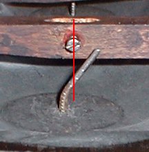 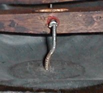 Figures 6 & 7 - Bending the Pin (Vertical Adjustments) Referring back to Figures 1 & 2, notice that the pins are not pointing straight up. In fact, one pin is leaning to the left and the other is leaning to the right. Accommodating these errors was actually handled when the first and second bends were put into the pin. Unfortunately, due to the angles at which the pictures were taken, this fact is not obvious. However, as seen in the pictures below (See Fig 8 & 9), the lever can be used as a straight edge to determine if the pins are correctly positioned in the vertical plane. Figures 6 & 7 show the positioning of the pins in the horizontal plane.
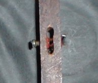
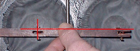  Figures 8 & 9 - Positioning the Pins Horizontally Sometimes the pins will be badly out of place. (See Fig 10) In such a case, it's important to determine where the pin should actually be located before you start bending the pins. This is easily done by measuring the width of the section and dividing by two. Once that's done, the pin can be bent in exactly the same manner as stated previously.
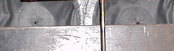 Figure 10 - Locating the Center Now that the pouch pins have been correctly positioned, they will slip into the wire keepers without any effort and each lever will be in the 'geographical' center of its associated section. For the time being, connect the pouches to the levers, allowing from 1/16"-1/8" of the pin to protrude through the wire keeper. (You might have to change the position of the pouch later, so don't over-tighten the set screws.) Move each of the levers up and down a few times to see how it feels. Also note how far each lever will move in both directions (up and down). This will be important shortly. At this point, you need to do a little bit of detective work. Specifically, you need to examine the linkage that goes between the levers and the crankshaft. Upon close examination, you will no doubt see the indentation in the pin that was made by the set screw. With any luck, there will only be the one mark that was made when the motor was constructed at the factory some 80+ years ago. (See Fig 11) Using the mark as your guide, attach the connecting rod to the lever, and note the spacing between the bottom edge of the motor and the lever when the crankshaft is positioned so that the lever is located as close as possible to the bottom edge. (See Fig 12) This distance should be almost identical on all three levers. Here again, do not over-tighten the set screws. With regards to the woven felt bushings in the holes for the set screws, if they need to be replaced, the hole size is 19/64". The correct bushing cloth is 0.054" thick and the width is 7/8". Remember, when replacing the bushing cloth in holes, the strips of cloth must be ripped, not cut.
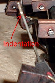 Figure 11 - The Indentation 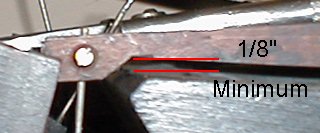 Figure 12 - Spacing the Lever to the Block In the next step, the connecting rods get positioned in the center of their respective crankshaft lobe. In Figure 14 you can see that the connecting rods on the right and left are both positioned to the left of center, whereas the rod in the center is where it belongs -in the center of the lobe. Also notice the bend in the pouch pin in the center section of the motor. If you look carefully, you will see that even though the pouch pin is bend rather significantly, the lever itself is right in the center of the section and, since the connecting rod is nice and straight, it's right in the center of the lobe. However, even though it isn't plainly visible in the picture, the left and right connecting rods have slightly different problems. The rod on the left is actually bent where the wire goes into the wood, and the wire itself is also bent. As it turned out, the wire was not screwed into the wood all the way, and while tightening it up, it was obvious that it was not straight. It was also found that the wire that connects to the sliding valve was applying pressure to the connecting rod, pulling it to the left. So, it was disconnected. I also disconnected the other two wires because I realized that the pressure, or tension, of those wires might be effecting the position of the connecting rods. (See Fig 13) NOTE: I know I said at the very beginning that all of the wires should be disconnected before starting. And this situation, which became apparent well into the adjustment process, is precisely why I made that statement. However, by the time I realized the importance of disconnecting everything, the pictures had already been taken, and I couldn't go back and start over.
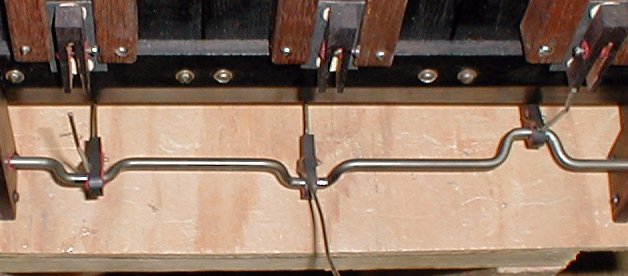 Figure 13 - Finding the Actual Position of the Connecting Rods At this point, I also made a couple of other discoveries. Notice that the wires leading to the valves have some significant bends. I can only assume that this was done to accommodate the various components that were not correctly aligned when the motor was restored. Also notice that the position of the left connecting rod is even worse than it was in the previous picture. The point here is that the pressure on the sliding valve was severe. In fact, it was so severe that it was lifting the valve off of the block when there was no vacuum applied. This made it impossible for the motor to work at low vacuum levels....
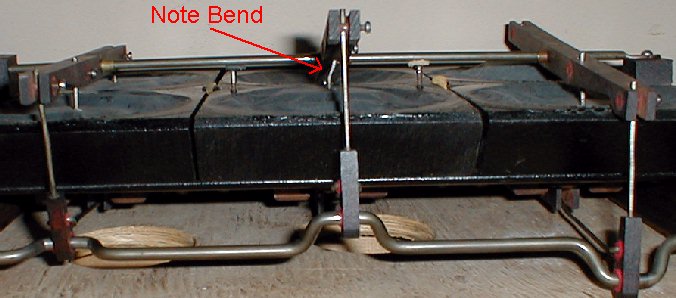 Figure 14 - Aligning the Connecting Rods As you can see in the next three pictures (See Fig 15-17), the wires were bent as necessary to center all three connecting rods. In Figure 16 you'll note that the rod still isn't perfectly straight. Further adjustments were made before Figure 17 was shot. This brings me to an important point. Adjusting the position of the connecting rods involves lots of testing. After each adjustment is made, the crankshaft must be rotated at least a few times to see where the rod will 'settle'. (I always rotate the shaft in the same direction as it will turn while in actual operation.) I prefer to make small adjustments a few times instead of trying to make one big adjustment and then have to go back and undo it...
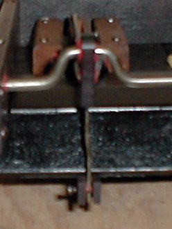 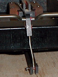  Figures 15-17 - Centering the Connecting Rods Now you need to rotate the crankshaft through all 360 degrees of rotation and see how things 'feel'. Ideally, everything should feel smooth and the crankshaft should rotate without any resistance. It's also wise to rotate the crankshaft to the point where each pouch is at its highest and lowest point in its associated well. While it's there, feel the cloth with your fingers. Under no circumstance should the cloth feel taught. It should always have a little more 'give', or room to move a little further (either 'in' or 'out'). If by chance you do encounter a pouch that is a little taught, loosen the set screw and adjust the position of the pouch to relieve the condition. Then move the pouch to the other extreme and check it again. If you have a problem getting a pouch to conform to the above conditions, you can change the position of the lever by adjusting where it's secured to the connecting rod. However, if you have to resort to changing the position of a lever, chances are that the pouch should be done over again. The final step is the adjustment of the wires that go from the connecting rods to the sliding valves. Normally, this isn't very difficult. Especially since you've had quite a bit of practice while getting to this point. However, there are a few pointers that will help get the job done right. First, insert the wires into their respective valve wire keeper, but don't tighten the set screws. Now position yourself so that you're looking at the side of the motor and looking across the face. (See Fig 18) While you're there, rotate the crankshaft through all 360 degrees of rotation. What you don't want to see is what is pictured in Figure 18. Note that the rod protrudes beyond the sides of the motor. Also notice the two screws in the front of the sides. Those screws hold the face plate in place. If the wires were left as in the picture, the valve wire would run into the face plate. So, the wire needs to be bent slightly. You'll also notice that the wire has a rather significant bend at each end. Those bends belong there!! If you must 'un-bend' the wire, do so just enough so that the wire won't touch the face plate and 'un-bend' each end an equal amount. Don't get carried away here.... (Also, refer to Figure 26)
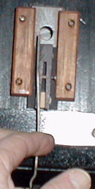
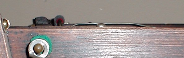 Figure 18 - Adjusting the Valve Wires - Step One The next adjustment is what I call the 'side-to-side' adjustment. Because of the way the wires are attached to the wooden portion on the connecting rod, they are not rigid. In fact, they will move side-to-side with relative ease. If the wire is adjusted correctly, it will move from side-to-side an equal distance. (See Fig 19-20) However, you may find that a wire will move more easily to one side of center than the other. (See Fig 21-22) If that's the case, the wire needs to be bent. There are a number of ways to attack the problem depending on how much time and effort you're willing to expend. However, the best approach is to remove the wire and examine it for any irregularities. (See Fig 23) When the wire was first bent at the factory, they no doubt had a template and every wire was virtually identical. That being the case, and since we have no template to work with, we must employ some logic and common sense to return it to its former shape. In Figure 24, I have drawn a simple diagram to illustrate what I believe was the logic that Lauter used. It makes sense that the center of the area which is fastened to the wooden portion of the connecting rod be in a straight line with the other end of the wire, which is connected to the valve. Therefore, it makes sense that there is one 90 degree bend and two 45 degree bends in the wire. (Note: In the wires I have measured, the bend which keeps the wire from falling out of the wooden portion seems to be a consistent 45 degrees.)
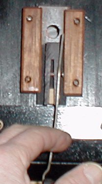  Figures 19 & 20 - Moving the Wires Side-To-Side (First Set)
  Figures 21 & 22 - Moving the Wires Side-To-Side (Second Set)
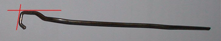 Figure 23 - Irregularities in the Bends
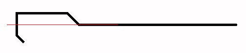 Figure 24 - Optimum Bends in the Wire With a little bit of time, the wire can be reshaped so that it looks like the one in the pictures below. The main thing to note is that the angles and shape of the wire are relatively uniform. The basic logic being that everything will have a natural tendency to move in a straight line as opposed to some arbitrary angle. That being the case, the energy created by the pouch will be transferred most directly and uniformly to the crankshaft.
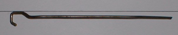 Figure 25 - Correctly Bent Wire #1
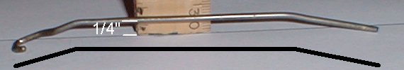 Figure 26 - Correctly Bent Wire #2 (go back) When you're all done and the wires have been put back in place, they should all be resting comfortably in the center of their respective valve guides. (See Fig 27) They should also have an equal amount of side play. If they are not straight or the side play is not equal, slight corrections can be made in the primary bends.
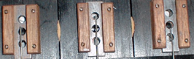 Figure 27 - Valve Wires Correctly Positioned At last we come to the sliding valves. Most simply put, they should be attached to the valve wires such that they oscillate an equal distance back and forth across the center hole (vacuum supply hole) as the crankshaft is rotated through all 360 degrees of rotation. Correctly positioning them is best accomplished by trial-and-error, so don't over-tighten the set screws until you're certain the valves are in the right place. If you do over-tighten the set screws, making a slight adjustment one way or the other will be extremely difficult because the set screw will have a natural tendency to find its way into the previous indentation in the wire. As a matter of fact, it may have a tendency to do that anyhow because of the indentation that was made in the wire when the motor was first assembled. If that happens, and you just can't seem to get the valve to sit in the right place, there are two options. One, file the wire and remove the old indentation. Two, increase or decrease the bend in the wire that is closest to the valve. I refer to this as "fine tuning" the wire. This should only be done if you are moving the valve 1/16" or less. Adjustments of more than 1/16" should be done by using the set screw. Once that's done, it's time to run the first functional test. Connect a regulated vacuum source to the main vacuum supply flange. For the initial test, set the vacuum level between 7"-10". Let the motor run for a few minutes and then start decreasing the vacuum level. If the sliding valves and the block were correctly flattened while the motor was all apart and everything has been well adjusted, the motor should run extremely smoothly on as little as three inches (3") of water vacuum. If it does, you have done an excellent job. However, this is rarely the case. And, as you will see shortly, it's very wise to run the motor under a slight load for at least ten minutes and then examine the sliding valves. [I made up a simple tool for applying a load to the crankshaft. (See Fig 28a & 28b) You can also hook the motor up to the transmission and put the transmission in the Rewind mode. This will apply a slight tension to the motor via the Rewind Brake mechanism.] Unless you've done a perfect job of flattening the valves and block, what you will see on the sliding surface of both the block and the sliding valve is some sort of an irregular pattern or "footprint". What the footprint tells you is where the two pieces of wood are actually touching each other. (See Fig 29) Notice the voids in the footprints. This is where air is leaking into the motor. Fixing the problem will require patience and tenacity.
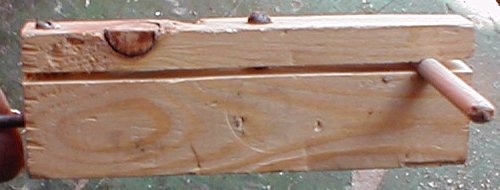 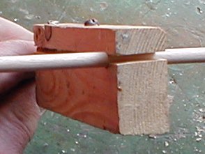 Figure 28a & 28b - Tool For Applying A Load to the Motor Crankshaft
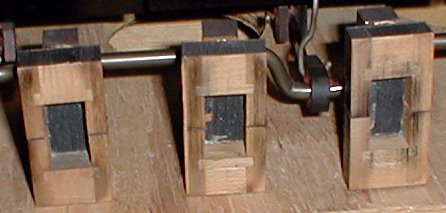 Figure 29 - 'Footprints' on the Sliding Valves The best way to fix the sliding valves is to put a piece of 400-600 grit sandpaper on a piece of plate glass (at least 3/8" thick) and gently lap the surface of the valve. Examine the surface after each pass. Below is one that is almost done, and next to it is the finished set. 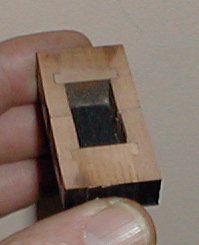 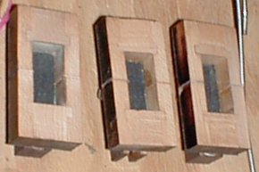 Figure 30 - 'Lapping' (Re-Surfacing) the Sliding Valves Now assemble the valves and test them again. After running the motor for awhile under a load, examine the valves again. If the footprints are even, then the valve block must be resurfaced. Use the same technique as was used to resurface the sliding valves. After finishing, apply a coating of powdered graphite with your finders, rubbing it into the grain of the wood. For best results, mix the graphite with a small amount of alcohol and make a paste. Then work that into the grain and let it dry. Then, using a razor blade, carefully remove any excess graphite. Then very lightly sand the surface with 600 grit paper. When you're sure that both the sliding valve and the block are flat, work some powdered graphite into the surface of the sliding valves and finish assembling the motor. |
Now Playing: "Thunderin' Love", by John A. Tuttle.

![]() ..To
The Top of this Page . . . . . . . . . . .
..To
The Top of this Page . . . . . . . . . . . ![]() ..To The HOME Page
..To The HOME Page
|
Since "Player-Care" is an internet business, I prefer that we correspond via E-Mail (click here to fill out the 'Request Form'). However, if I'm not in the middle of some other activity, you can reach me at 732-840-8787. But please understand that during the hours from 8AM-5PM EST (Mon-Sat), I'm generally quite busy. So, I probably won't answer the phone. If you get the answering machine, please leave a detailed message stating the reason for your call. Also, repeat your name and phone number clearly and distinctly. By necessity, I prioritize everything in my life. And, if you call and just leave your name and number, and ask me to call you back, it might be a day or two before I return your call. Why? Because I don't know why you want me to call and I might not be prepared to assist you in an effective and efficient manner. If you leave me an E-Mail address (which I prefer), spell it out phonetically. The more you do to help me, the more I can help you in return. Don't rush. You have four minutes to record your message. |
|
407 19th Ave, Brick, NJ, 08724 Phone Number 732-840-8787 (Voicemail Only, No Texts) |
