|

|

|
|
|
|
|
| Home | Manuals | Supplies | Search | Consult | Contact | Testing | Service |
Lauter-Humana Diagram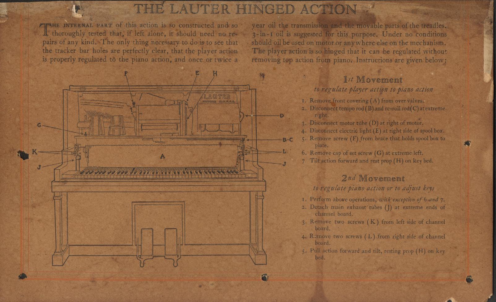 Click on Picture to see FULL Picture.
The diagram was found in a Lauter-Humana by COL. Scott Slauson. Scott also did the scanning of the document. I scaled it down to fit on this page, which made it illegible. However, the original full-scale image is very legible. Also, thanks to the efforts of Steve Davis, the full-scale image appears as it did originally. The picture is still split into three parts. Simply click on the part of the picture you wish to view from the diagram below. To return to this page after viewing, click your BACK button.  Scroll Down for More Information For those of you that have never worked on a Lauter-Humana, I am including a few additional steps which are not mentioned in the original text. I have also taken the liberty of editing the drawing of the piano (piano1.jpg) to include the location of the four screws that hold the facia board (marked in red) to the main platform and the six screws that hold the valve cover to the valve mounting board. The screws are marked in yellow. The blue boxes are mounted to the valve cover. Before the Valve Cover can be removed, the Facia Board must be removed (see rectangle marked in red). There are four screws holding the board in place (marked with yellow dots above rectangle). Once removed, three of the screws that hold the Valve Cover in place are exposed (marked with slightly larger yellow dots). The other three screws, which must also be removed, are located near the top edge of the Valve Cover (see blue rectangles with small yellow dots). When all six screws are removed, the Value Cover can be taken out of the unit. Be careful not to damage the Volume Indicator Pneumatic or Tempo Linkage when removing the Valve Cover. Regarding the Text, which can be a little difficult to read. Here is the same text, clearly written. 1st Movement to regulate player action to piano action
1. Remove front covering (A) from over valves. 2nd Movement to regulate piano action or to adjust keys
1. Perform above operations, with exception of 6 and 7. |
|
Since "Player-Care" is an internet business, I prefer that we correspond via E-Mail (click here to fill out the 'Request Form'). However, if I'm not in the middle of some other activity, you can reach me at 732-840-8787. But please understand that during the hours from 8AM-5PM EST (Mon-Sat), I'm generally quite busy. So, I probably won't answer the phone. If you get the answering machine, please leave a detailed message stating the reason for your call. Also, repeat your name and phone number clearly and distinctly. By necessity, I prioritize everything in my life. And, if you call and just leave your name and number, and ask me to call you back, it might be a day or two before I return your call. Why? Because I don't know why you want me to call and I might not be prepared to assist you in an effective and efficient manner. If you leave me an E-Mail address (which I prefer), spell it out phonetically. The more you do to help me, the more I can help you in return. Don't rush. You have four minutes to record your message. |
|
407 19th Ave, Brick, NJ, 08724 Phone Number 732-840-8787 (Voicemail Only, No Texts) |