|

|

|
|
|
|
|
| Home | Manuals | Supplies | Search | Consult | Contact | Testing | Service |


Lauter-Humana
|
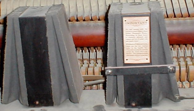 Lauter-Humana Tracking Assembly w/covers on Do not tamper with the valves or connections in these Shifter Pneumatic Boxes. Everything in these boxes is correctly adjusted and cannot get out of order - do not touch them! |
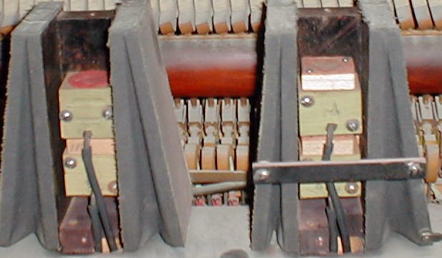 #1 Lauter-Humana Tracking Assembly w/Valves Showing
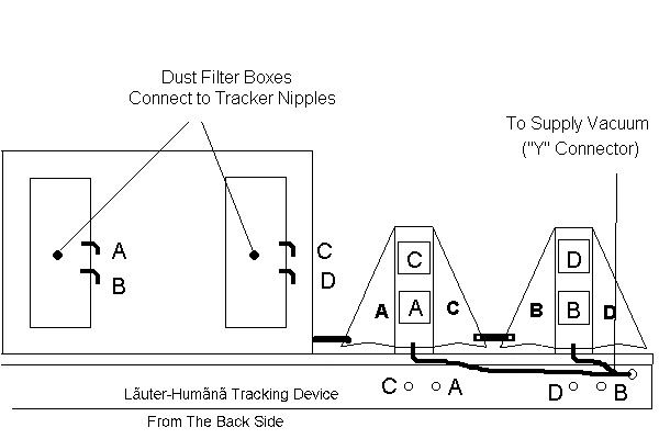 #2 Bellows are not shown in their proper orientation...
#3 Valve Tubing and Orientation
The Lauter-Humana Tracking System is unlike any other system. While it has four valves and four bellows, there are only two tracking holes in the trackerbar. As shown in the above diagram #2, both of the tracker holes in the trackerbar are connected their own dust filter. Then, any signal from the tracker hole is equally split into two signals and each signal is sent to one of the two valves in each shifter box. As can be seen in Picture #1, the bellows in the shifter on the right are tied to each other such that if one bellows closes, the other bellows opens. What's not clear is what happens to the bellows in the other shifter. As demonstrated in the two pictures below (which are taken from the back of the tracker assembly as it sits in the piano), you can see that as the shifter bellows on the left move from one extreme to the other, the shifter bellows on the right either open or close equally. 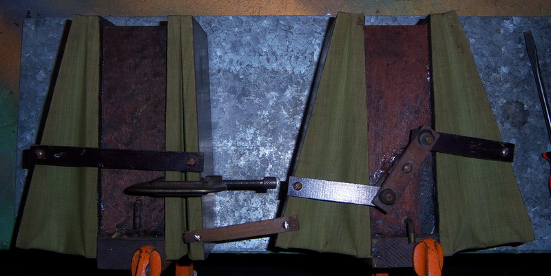 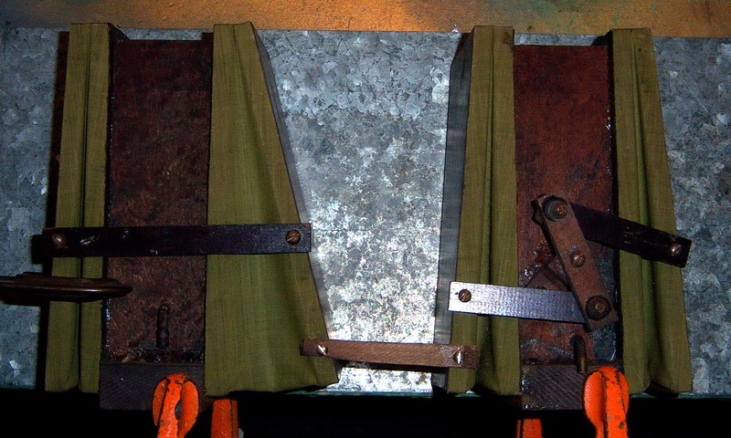 The obvious question that comes to mind is: If you have a two-hole tracking system and you have one set of shifter bellows that move right or left when triggered by the opening or closing of the trackerbar holes, what's the purpose of the second set of shifter bellows? To answer that question, we have to understand how the four valves work. Referring to diagrams #2 and #3, we can see that Valves A, B, and C look the same while Valve D looks different. As it turns out, Valve D is the only 'normal' valve in the system. The other three valves are known are 'outside' or 'reverse' valves. Most simply put, that means that when the valve is 'off', vacuum flows through the valve and sucks the air out of the associated bellows -causing it to collapse or close. And, when the valve is 'on', atmosphere is allowed to flow back into the bellows -allowing it to relax, or open. With all the above being the case, we begin to see why Lauter didn't use just one shifter assembly. Had they used just two bellows adn two regular valves and both tracker holes were closed, the bellows would center. They wouldn't track the roll at all. The tracker wouldn't start working until one of the holes opened. Conversely, if both holes were open, again the bellows would center and nothing would happen until one of the holes closed. This brings us to the video below, which shows what happens under various conditions. The explanation of why Lauter designed the system in this fashion will be explained in greater detail below.
So, the next obvious question is: Why did Lauter design a tracking system that pulls to the left when both tracker holes are either open or closed? Actually, there are three answers. First, since all player pianos have a spring-loaded roll chuck on the left, there is a natural tendency for the music roll to track to the right. Therefore, the tracking system compensates for that natural tendency by applying an opposing force. Secondly, it prevents the system from ever becoming 'static'. In other words, there can be no condition in which the tracker mechanism isn't working. As noted previously, if there were only two regular valves and two shifter bellows, there would potentially be two conditions in which the mechanism wouldn't be doing anything at all. Lastly, it sets up a condition in which the system becomes extremely sensitive. Just below are pictures which show that position of the music roll on the trackerbar during actual operation.
Adequate Roll Tracking
Vacuum Readings while Testing the Tracking System Lastly we come to the four shifter block valves mentioned earlier. As noted previously, valve 'D' is the only 'ordinary' valve in the system. The other three (A, B, and C) are outside valves. Shown below is the difference between the two types of valves.
Now things start getting a little complicated. Since there is no patent information that I've been able to find, figuring out what the inventor was trying to accomplish requires some logical thinking. The first thing we have to establish is fairly obvious. The shifter assembly on the left (with valves B and D) can only pull the music roll to the left. As shown in the video, it can pull the roll gently to the left or it can pull it more forcefully to the left. If the roll is tracking 'too far' to the left, the left shifter simply relaxes. What is also important to note in the pictures above is the size of the hole in the upper left area of the outside valve. It's important because there is a hole of equal size leading from there to the valve's associated bellow. The holes leading to the bellows in the left shifter box are identical in size. So, the full force of the applied vacuum is felt in those bellows when the valves are actuated. The importance of this fact will be seen later in the discussion. But remember that when both tracker holes are either open or closed, the system favors the left side. Here is a picture of the 'vacuum restrictors' in the shifter box on the right. There are no restrictors in the shifter box on the left. 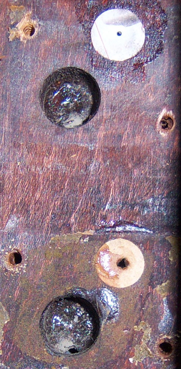 Restrictor holes leading to bellows (this part is under construction) Turning our attention to the right shifter box, recall that both valves (A and C) are outside valves. In the video, we saw how the tracking system is designed to........ (this part is under construction) Like every other player piano system manufacturer, Lauter wanted to utilize patented mechanisms of their own design. In November of 1913, they applied for the following patent, which was approved on October 20, 1914. While it's obvious that this is nothing like the mechanism that Lauter ultimately created, the one aspect of the design that remained throughout production was the connecting rod (#18) that went through the spoolbox and the lever (#20). See the picture below. As a side note, although I've never seen it mentioned anywhere, an interesting facet of the connecting rod is that it allows an experienced user to manually track a problem roll. If a roll starts going off track, the user can simply grab hold of the rod and move the roll in the desired direction. No other system I'm aware of offers the user such a capability.
|

![]() ..To
The Top of this Page . . . . . . . . . . .
..To
The Top of this Page . . . . . . . . . . . ![]() ..To The HOME Page
..To The HOME Page
|
Since "Player-Care" is an internet business, I prefer that we correspond via E-Mail (click here to fill out the 'Request Form'). However, if I'm not in the middle of some other activity, you can reach me at 732-840-8787. But please understand that during the hours from 8AM-5PM EST (Mon-Sat), I'm generally quite busy. So, I probably won't answer the phone. If you get the answering machine, please leave a detailed message stating the reason for your call. Also, repeat your name and phone number clearly and distinctly. By necessity, I prioritize everything in my life. And, if you call and just leave your name and number, and ask me to call you back, it might be a day or two before I return your call. Why? Because I don't know why you want me to call and I might not be prepared to assist you in an effective and efficient manner. If you leave me an E-Mail address (which I prefer), spell it out phonetically. The more you do to help me, the more I can help you in return. Don't rush. You have four minutes to record your message. |
|
407 19th Ave, Brick, NJ, 08724 Phone Number 732-840-8787 (Voicemail Only, No Texts) |